Defoaming sonotrode system

a sonotrode and foaming technology, applied in the direction of mechanical vibration separation, separation process, packaged goods, etc., can solve the problems of unsatisfactory product loss, high cost for consumers or bottlers, and undesirable product loss

Inactive Publication Date: 2009-11-12
NEW SONIC TECH
View PDF15 Cites 3 Cited by
  • Summary
  • Abstract
  • Description
  • Claims
  • Application Information

AI Technical Summary

Benefits of technology

[0015]One feature of the sonotrode of the present invention is the capability of the sonotrode to achieve additional gains in amplitude through external means that boost the amplitude without changing the inherent gain rate of the sonotrode itself. The sonotrode can be included in a system capable

Problems solved by technology

The product loss can reach as high as ten percent, which translates into higher cost for the consumer or lower profitability for the bottler, or both.
Other filled products are purposefully overfilled to compensate for lost product in the form of foam and thereby achieve the desired net fill volume, which results in undesirable product loss.
This results in a concentration of the radiation on the foam structure.
Thus there is an unsatisfied need for an operating single defoaming sonotrode that can effectively eliminate foam from the t

Method used


Image

  • Defoaming sonotrode system
  • Defoaming sonotrode system
  • Defoaming sonotrode system

Examples


Embodiment Construction

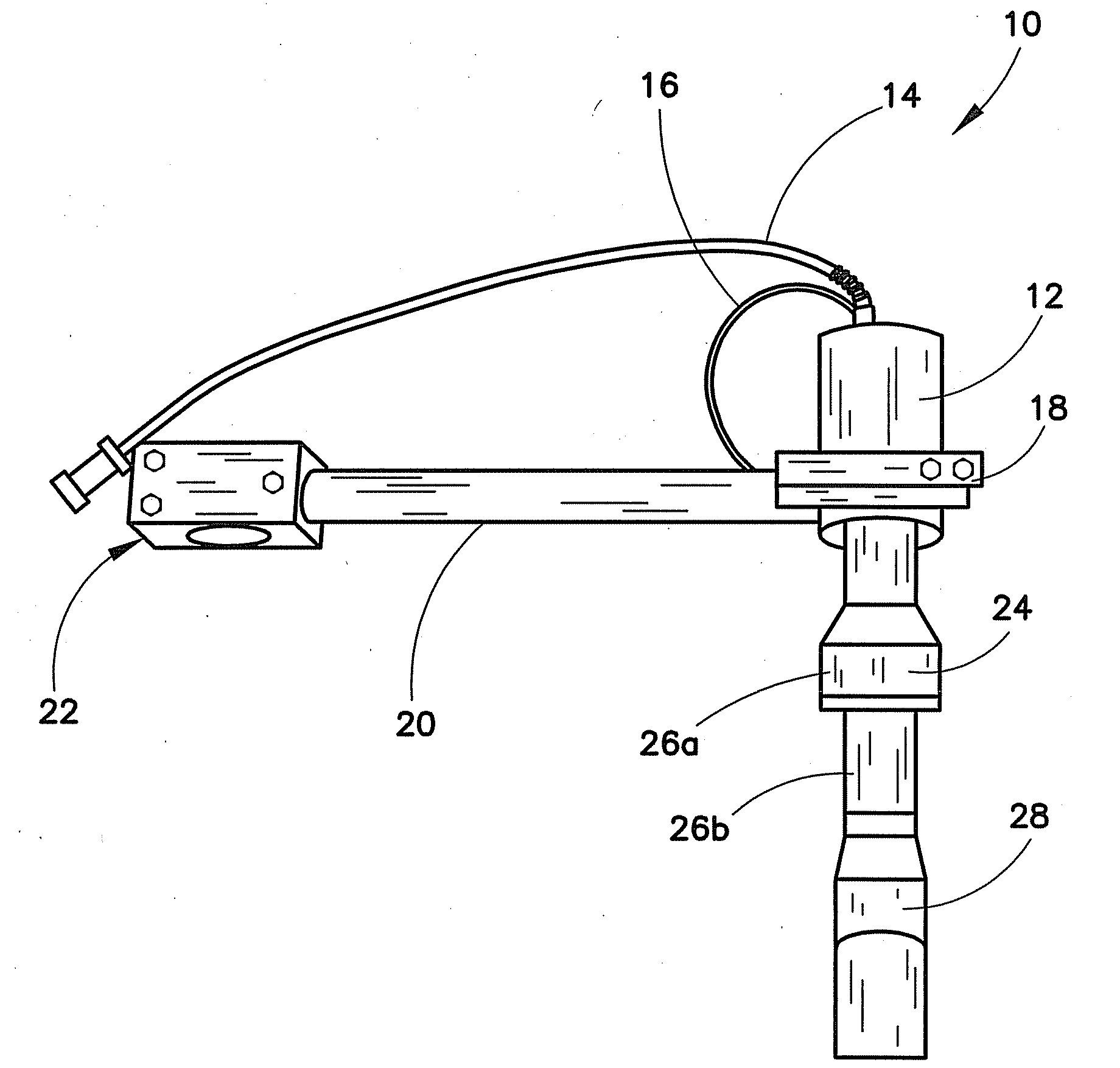
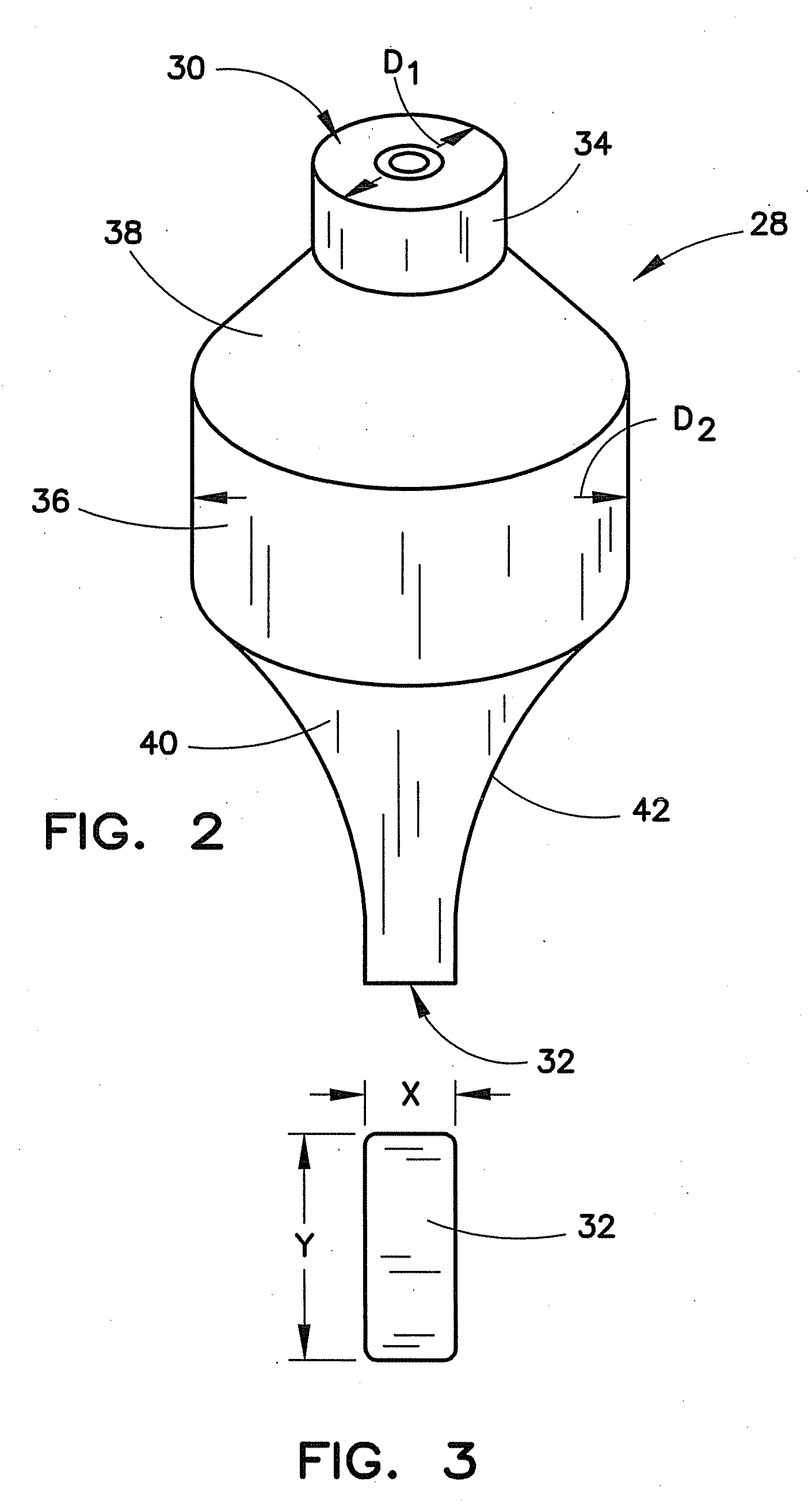
[0028]A sonotrode assembly 10 can have an ultrasonic transducer 12 that includes a control input 14 for supplying power to the transducer 12 as shown in FIG. 1. The assembly 10 can also include a line 16 for supplying coolant to the transducer 12. The coolant can be air or other gas that may be chilled and / or pressurized and caused to flow through the line 16 from a remote source. The assembly 10 can also include a support 18 fixed to the transducer 12 including a member 20 extending from the support 18 to a fixture 22 designed for attachment to a stand, post, stage or platform, not shown. An ultrasonic stack 24 can be provided, which can include a number of intermediate elements 26a, 26b, to couple the transducer 12 to a sonotrode 28.

[0029]A sonotrode assembly 10 is schematically shown in FIG. 4 to have an ultrasonic transducer 12 that includes a control input 14 for supplying power to the transducer 12. The assembly 10 can also include a line 16 for supplying coolant to the transd...


PUM

PropertyMeasurementUnit
Timeaaaaaaaaaa
Timeaaaaaaaaaa
Lengthaaaaaaaaaa

Abstract

A sonotrode specially adapted for defoaming liquids during container filing operations, has an upper body portion having a first diameter and having an upper face adapted to be mounted to a driving transducer, a middle body portion having a second diameter larger than the first diameter situated below the upper body portion, a generally conical portion situated between the upper body portion the middle body portion, and a transition portion situated between the middle body portion and a lower face adapted to be directed toward a liquid upper surface within a container, the lower face being generally rectangular.

Description

CROSS-REFERENCE TO RELATED APPLICATION[0001]This application is related to, and claims all available benefit of, U.S. provisional application Ser. No. 61 / 051,376 filed May 8, 2008.BACKGROUND OF THE INVENTION[0002]1. Field of the Invention[0003]The present invention generally relates to methods for limiting or controlling the foam above the top surface of a liquid. More particularly, the invention is directed to a methods utilizing ultrasonic energy to control foam by breaking the surface tension of the bubbles creating the foam above the liquid. The invention has application in the filling of containers with carbonated beverages, including soft drinks and beer, where the control or elimination of foam can enable higher production speeds, improved yields, reduced energy costs and improved net content capabilities. Other uses include foam control during container filing with non-carbonated liquids including juices, teas, sports drinks, liquid cleaners and wine. The present invention i...

Claims


Application Information

Patent Timeline
IPC IPC(8): B65B3/22
CPCB01D19/02B65B3/22B06B3/00
Inventor WILLIAMSON, JAMES T.
Owner NEW SONIC TECH
Why Eureka
Try Eureka