Networked, wireless lighting control system with distributed intelligence

a wireless and intelligence technology, applied in signalling systems, instruments, light sources, etc., can solve the problem that web-based software does not make lighting control decisions, and achieve the effect of eliminating the tedious and time-consuming task of manually identifying

Active Publication Date: 2009-11-12
ABL IP HLDG
View PDF32 Cites 358 Cited by
  • Summary
  • Abstract
  • Description
  • Claims
  • Application Information

AI Technical Summary

Benefits of technology

[0010]In accordance with the invention, a lighting control system is provided that effectively integrates time-based, sensor-based, and manual control with distributed intelligence throughout a building or building complex. As used herein, distributed intelligence means that all lighting control decisions, as well as all switching and dimming actions, are carried out by the devices within each individual “lighting zone.” A lighting zone may be, for example, an individual room or office, a classroom, a manufacturing area, a lobby, or other defined area. Lighting zones include one or more intelligent devices such as, for example, occupancy sensors, daylight sensors, power packs, and manually-operated switches. The intelligence is provided by microcontrollers and firmware incorporated in preferably each device. Relays connecting/disconnecting power to lighting devices are located locally within the lighting control zone, such as, for example, in sensors and/or power packs. The manually-operated switches are connected in series with the lights (i.e., the load) and are typically mounted in a single gang wall unit that may also include a sensor and/or a relay. The lighting control system of the invention is “self-commissioning,” which means the system automatically searches for and identifies devices connected to it, thus eliminating the tedious and time consuming task of manually identifying each device in the system. The system can be wirelessly connected between light

Problems solved by technology

That is, the Web-based software does not make lighting control decisions—those decisions ar

Method used


Image

  • Networked, wireless lighting control system with distributed intelligence
  • Networked, wireless lighting control system with distributed intelligence
  • Networked, wireless lighting control system with distributed intelligence

Examples


Embodiment Construction

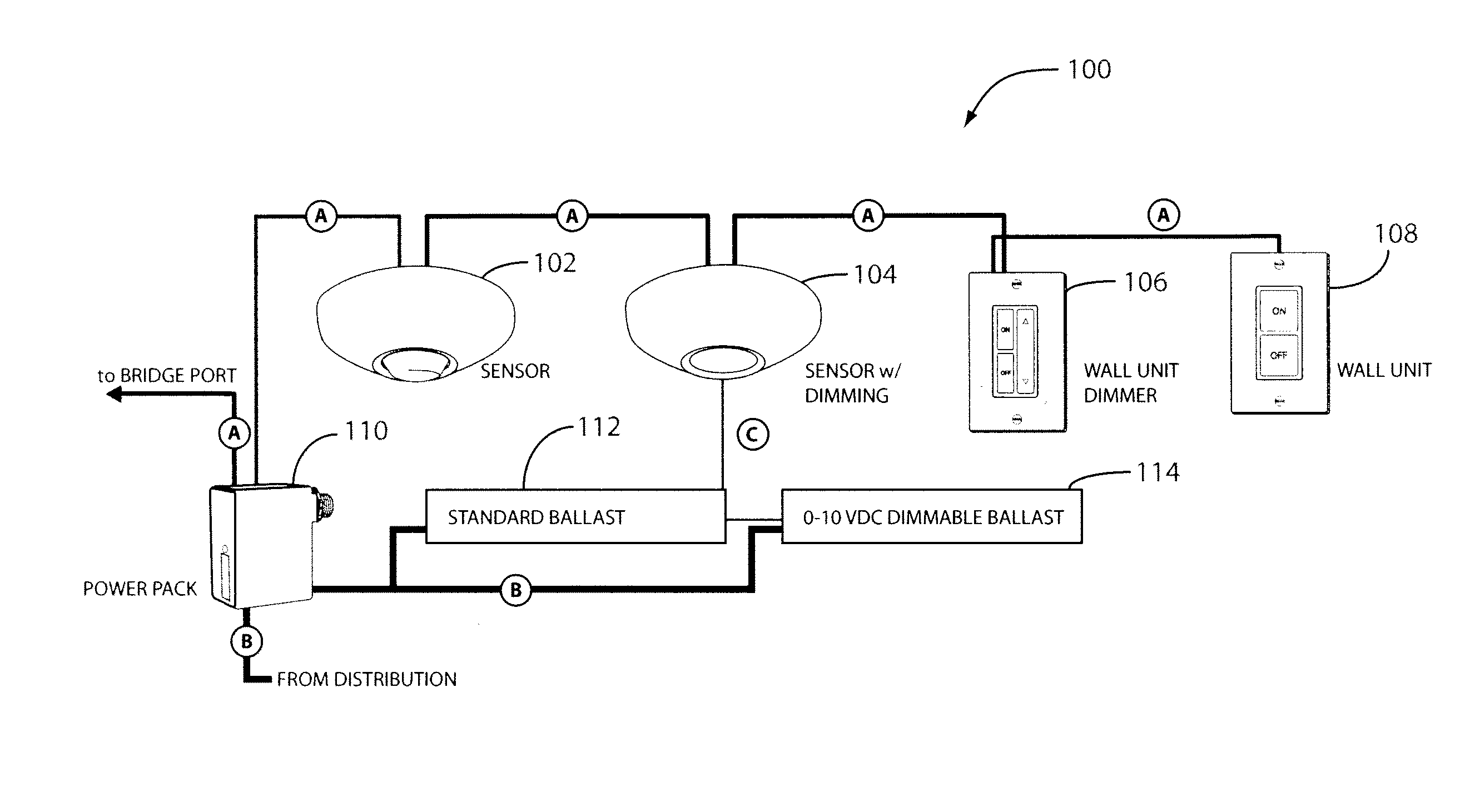
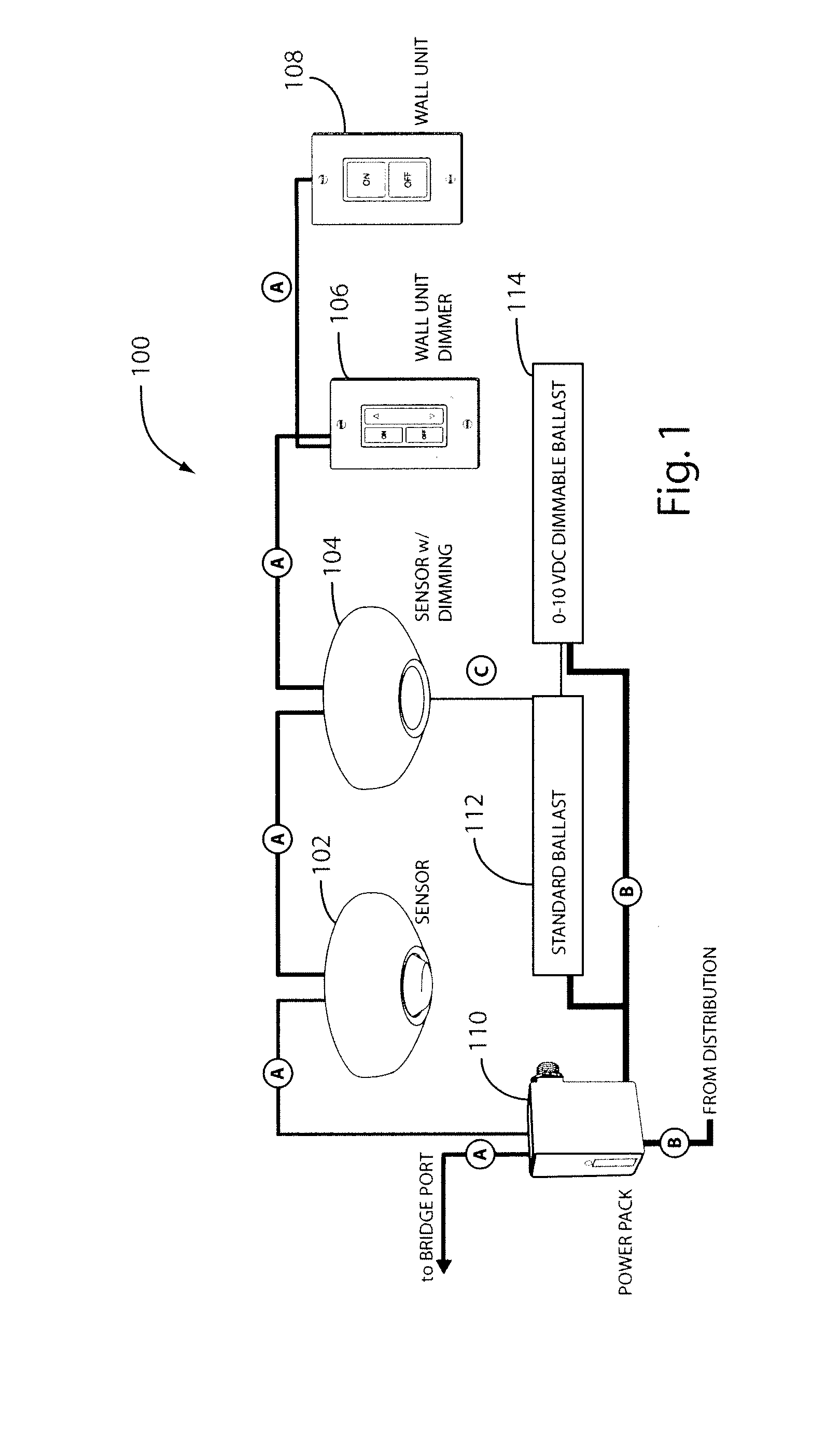
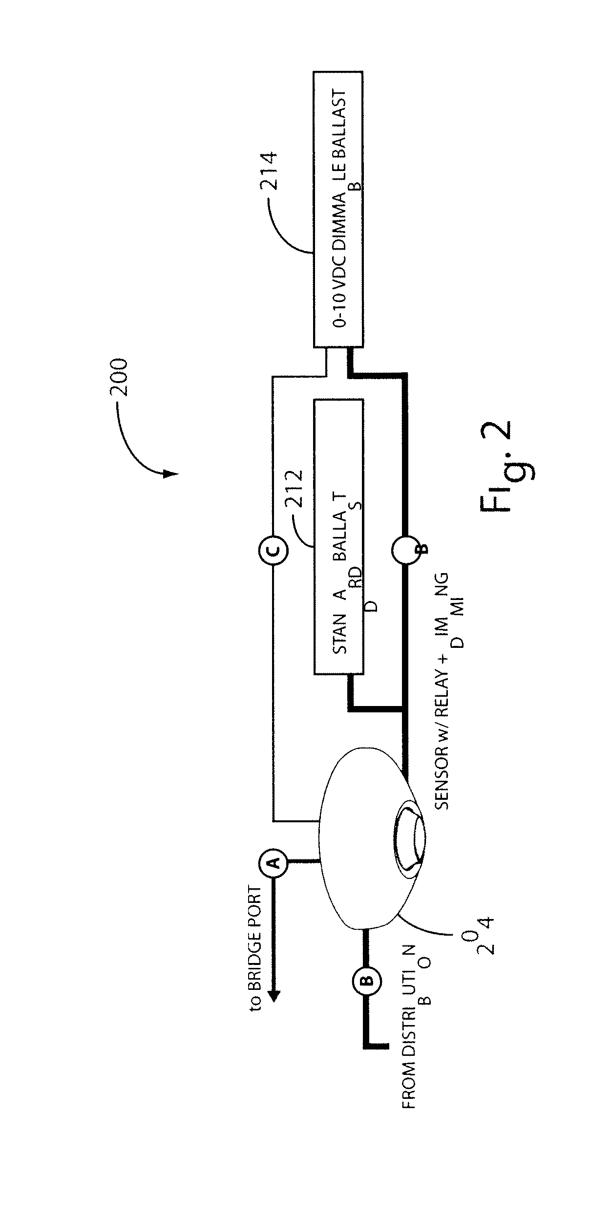
[0034]The lighting control system of the invention incorporates time-based, sensor-based, and manual control. Time-based control automatically switches lights on and off based upon preset time schedules or astronomical clocks. Sensor-based control automatically switches lights on and off based upon occupancy and / or daylight. And manual control switches lights on and off based upon manual toggling of a wall switch by a user.

[0035]The lighting control system of the invention advantageously provides numerous programmable settings / operational modes that can be configured individually for each lighting control zone. Settings include numerical device parameters, such as time delays for occupancy sensing and photocell set-points for daylight sensing. Other settings include switch operation (e.g., manual / automatic on), dimming limits, enable / disable sound detection, broadcast channel for switches and sensors (e.g., occupancy and daylight), and source channel for switches and sensors (e.g., ...


PUM


Abstract

A programmable lighting control system integrates time-based, sensor-based, and manual control of lighting and other loads. The system includes one or more groups of controlled lighting areas, which may be, for example, floors of a building. Each group may have one or more lighting zones, which may be, for example, individual rooms or offices on a building floor. Each lighting zone includes occupancy and/or daylight sensors that may be wirelessly coupled to a gateway of the group. Each gateway is coupled to a network, such as, for example, a local area network (LAN). Control software, residing on a computer (e.g., a personal computer or a server) coupled to the network and accessible via the network, remotely communicates with and controls the lighting zones either individually, groupwise, or globally. Each lighting zone can also be locally controlled at the gateway and can function independently of the control software and the gateway.

Description

FIELD OF THE INVENTION[0001]The invention relates to lighting control systems. More particularly, the invention relates to networked lighting control systems that use wired or wireless connectivity and distributed intelligence to control multiple zones of room or area lighting.BACKGROUND OF THE INVENTION[0002]Lighting control systems automate the operation of lighting devices throughout a building or residence based upon preset time schedules and / or occupancy and / or daylight sensing. These systems may also be used to automate the operation of other electrical devices or appliances ranging from, for example, simple fans to more complex HVAC (heating, ventilating, and air conditioning) systems. These systems may further be used in conjunction with fire and / or security systems. Lighting control systems typically employ occupancy sensors and / or daylight sensors to determine which lighting devices to activate, deactivate, or adjust the light level of, and when to do so. Occupancy sensors...

Claims


Application Information

Patent Timeline
IPC IPC(8): H05B37/00
CPCH05B37/0245H05B37/0218H05B37/0227H05B37/029H05B47/175H05B47/155Y02B20/40H05B47/13H05B47/11
Inventor PLATNER, BRIAN P.FASSBENDER, WILLIAM J.ZAVERUHA, RYAN A.RAMIREZ, FRANK J.GROSS, PHILLIP S.FRIGON, RAYMOND A.
Owner ABL IP HLDG
Why Eureka
Try Eureka