Apparatus and method for on-line detecting welding part of strip

Active Publication Date: 2009-11-12
POSCO
View PDF18 Cites 7 Cited by
  • Summary
  • Abstract
  • Description
  • Claims
  • Application Information

AI Technical Summary

Benefits of technology

[0019]According to certain embodiments of the invention as set forth above, a weld moving at a high speed can be easily detected on-line without using a through hole as in the prior art.
[0020]Furthermore, according to certain embodiments of the invention, since a through hole is not necessary, productivity of cold rolled products can be enhanced and probl

Problems solved by technology

However, this also needs to temporarily stop a corresponding line to perforate the steel strip 1, and thus productivity is lowered.
In addition, excess metal formed around the hole 5 damages or scratches the surface of a feed roll or mill roll.
Then, the scratched roll disadvantageously transfers a mark onto the surf

Method used


Image

  • Apparatus and method for on-line detecting welding part of strip
  • Apparatus and method for on-line detecting welding part of strip
  • Apparatus and method for on-line detecting welding part of strip

Examples


Example

[0030]Hereinafter preferred embodiments of the invention will be described in detail with reference to the accompanying drawings.

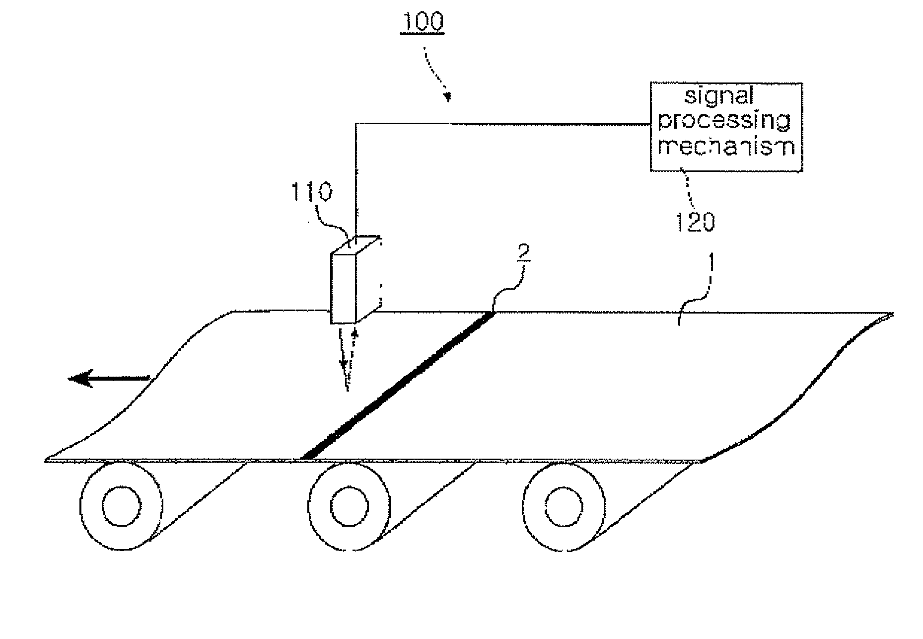
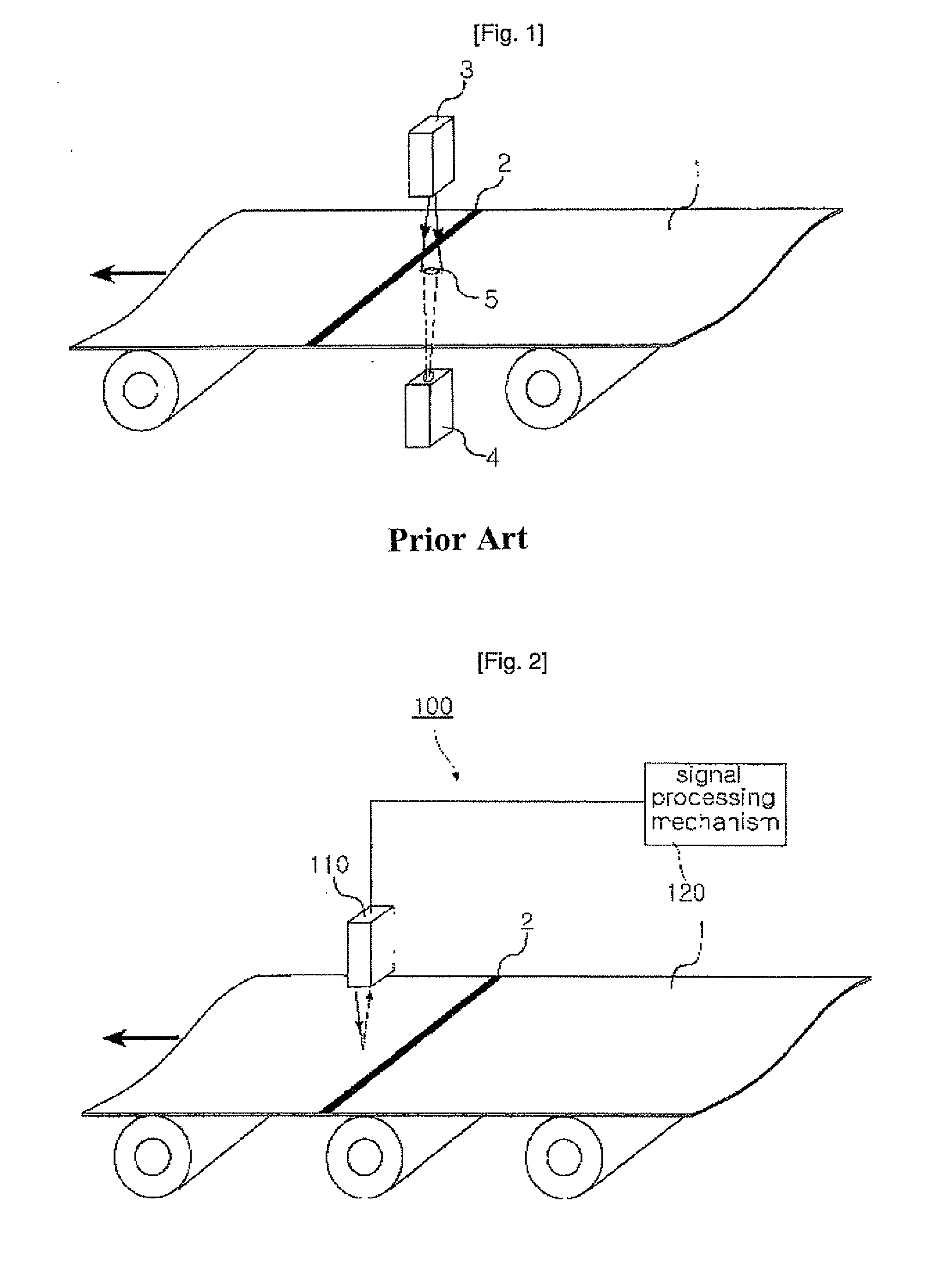
[0031]FIG. 2 is a schematic configuration view illustrating an on-line detection system for a weld of a steel strip according to an embodiment of the invention.

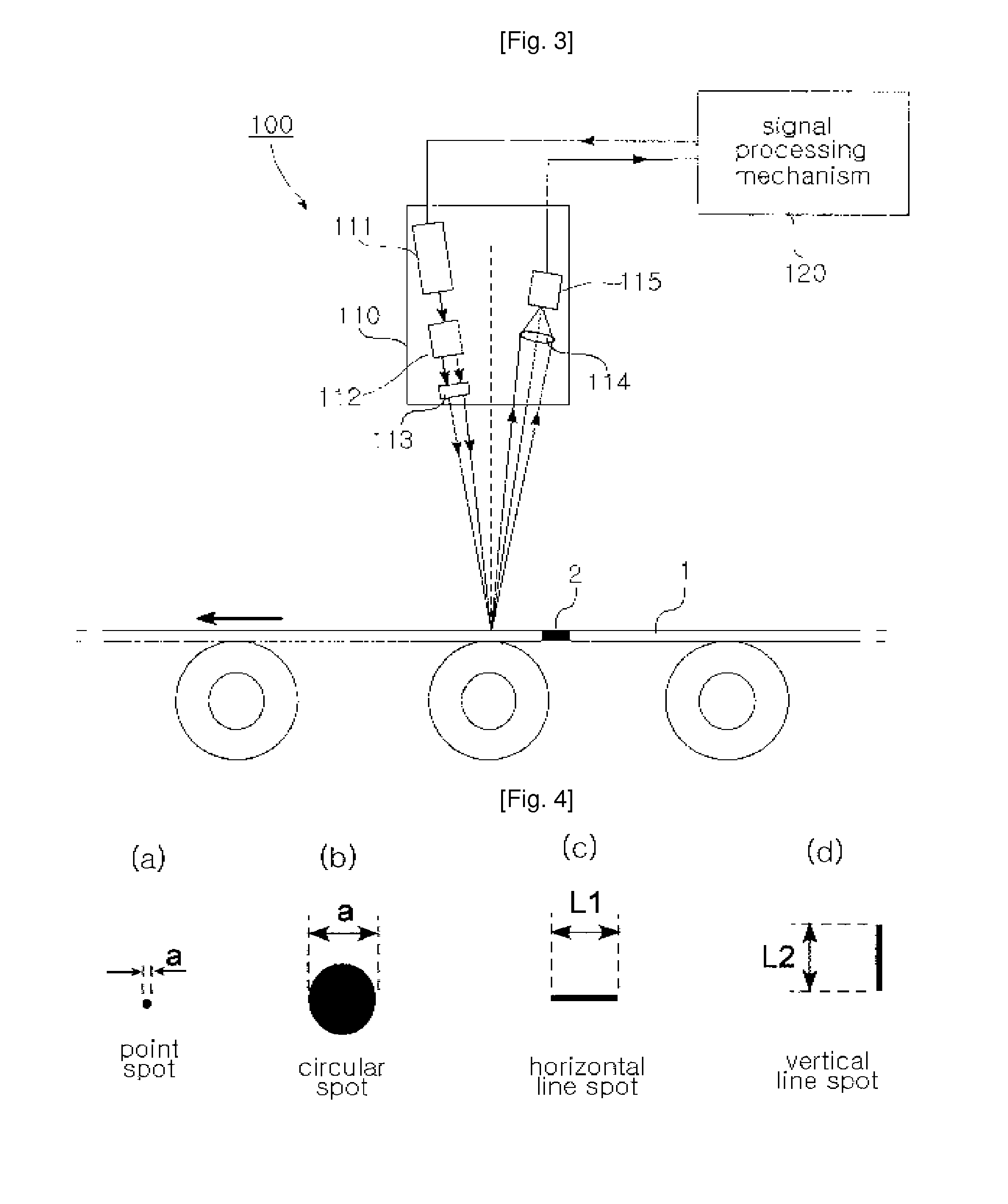
[0032]Referring to FIG. 2, the on-line detection system 100 for a weld of a steel strip of this invention includes a laser reflectivity measuring mechanism 110 and a signal processing mechanism 120. While a single one of the laser reflectivity measuring mechanism 110 is shown in the drawing, this is merely an illustrative embodiment of the invention. In another embodiment of the invention, two or more of the laser reflectivity measuring mechanism may be provided according to the width of the steel strip 1.

[0033]The laser reflectivity measuring mechanism continuously emits a laser beam onto a moving steel strip, which is being transported, and continuously measures the reflectivity of the laser beam ...


PUM

PropertyMeasurementUnit
Angleaaaaaaaaaa
Angleaaaaaaaaaa
Lengthaaaaaaaaaa

Abstract

There is provided an on-line detection system and method for a weld of a steel strip, which can emit a laser beam onto the surface of a steel strip moving at a high speed and measure the reflectivity of the laser beam reflecting from the same, thereby detecting the weld of the steel strip easily on-line. In the on-line detection system, reflectivity measuring means emits a laser beam onto a moving steel strip and continuously measuring the reflectivity of the laser beam returning from the surface of the steel strip, and signal processing means detects a weld of the steel strip based on change in the reflectivity measured on the weld.

Description

TECHNICAL FIELD[0001]The present invention relates to an on-line detection system and method for a weld of a steel strip, in particular, which scans a laser beam onto a steel strip moving at a high speed, and based on the reflectivity of the laser beam returning from the steel strip, locates on-line a weld of the steel strip.BACKGROUND ART[0002]Generally, in a cold rolling of an iron and steel mill, unit coils are welded together into a steel strip at a starting step of the cold rolling so that continuous rolling can be carried out, and the steel strip is cut along welds into the unit coils at a finishing step of the cold rolling, which are then transported to a following process or shipped as final products. Accordingly, in the cold rolling, it is inevitably required to locate such welds in order to automatically and precisely control essential process equipments and trim the steel strip along the welds into the unit coils at the output side.[0003]FIG. 1 is a detection system for a...

Claims


Application Information

Patent Timeline
IPC IPC(8): G01N21/47
CPCG01N21/55G01N2021/8918G01N21/89B23K31/12G01N21/47
Inventor LIM, CHOONG SOOSON, KI SAMSON, KWANG HOCHOI, SEUNG GAPLEE, SANG JINOH, KI JANG
Owner POSCO
Why Eureka
Try Eureka