
MIMO decoder and MIMO decoding method

a decoding method and mimo technology, applied in diversity/multi-antenna systems, amplitude demodulation, multiplex communication, etc., can solve the problems of detection errors, detection errors, and diversity gain, and achieve the effect of increasing the communication path capacity, reducing complexity, and increasing speed

Active Publication Date: 2009-11-12
NEC CORP
View PDF7 Cites 18 Cited by
  • Summary
  • Abstract
  • Description
  • Claims
  • Application Information

AI Technical Summary

Benefits of technology

[0020]In order to accomplish “whenever, wherever, and whoever,” which is an ultimate purpose in mobile communications, a signal separation in space signal multiplex, which is a measure for increasing the communication path capacity, must be implemented with a stable quality resulting from higher performance and with low complexity in radiowave propagation environments which vary from one minute to the next, even if a biased dispersion state unsuitable for MIMO is caused by a peculiar reflecting object.

Problems solved by technology

The fading phenomenon is always an impediment for accomplishing high quality mobile communications.
The conquest of poor radiowave propagation environment due to this fading has been a challenge in the mobile communication technologies over a long time, and a variety of countermeasures have been so far brought into practice.
However, since these methods perform (nT−1)-th null production in nulling-based linear processing at the first step, they have a problem that the diversity gain can be provided only on the order of nR−nT+1.
Therefore, detection errors are likely to occur at the first step, and its influence can cause error propagation which leads to detection errors at later stages.
However, in MLD, since the complexity exponentially increases with respect to the number of antennas and the size |A| of a modulation signal point, MLD is effectively impossible in consideration of coding.

Method used


Image

  • MIMO decoder and MIMO decoding method
  • MIMO decoder and MIMO decoding method
  • MIMO decoder and MIMO decoding method

Examples


Embodiment Construction

[0083]Next, preferred exemplary embodiments of the present invention will be described with reference to the drawings. First, a theoretical background of the present invention will be shown in an analytical fashion.

[0084]A variety of calculation amount reducing techniques have been conventionally known in MIMO systems, where the complexity thereof is attributable to a proper limiting process for a search area of a transmission signal vector which would has been transmitted from a transmission antenna, or a search area for each element in the transmission vector. Accordingly, first shown is that the proper search area differs in different radiowave propagation environments in an analytical fashion.

[0085]Assuming that a reception signal vector y(i) having nR reception antennas at sampling time i is represented by:

y(i)=[y1(i)y2(i)⋮ynR(i)],(1)

and a transmission signal vector s(i) having nT transmission antennas is represented by:

s(i)=[s1(i)s2(i)⋮snT(i)],(2)

then, using a channel matrix H...


PUM


Abstract

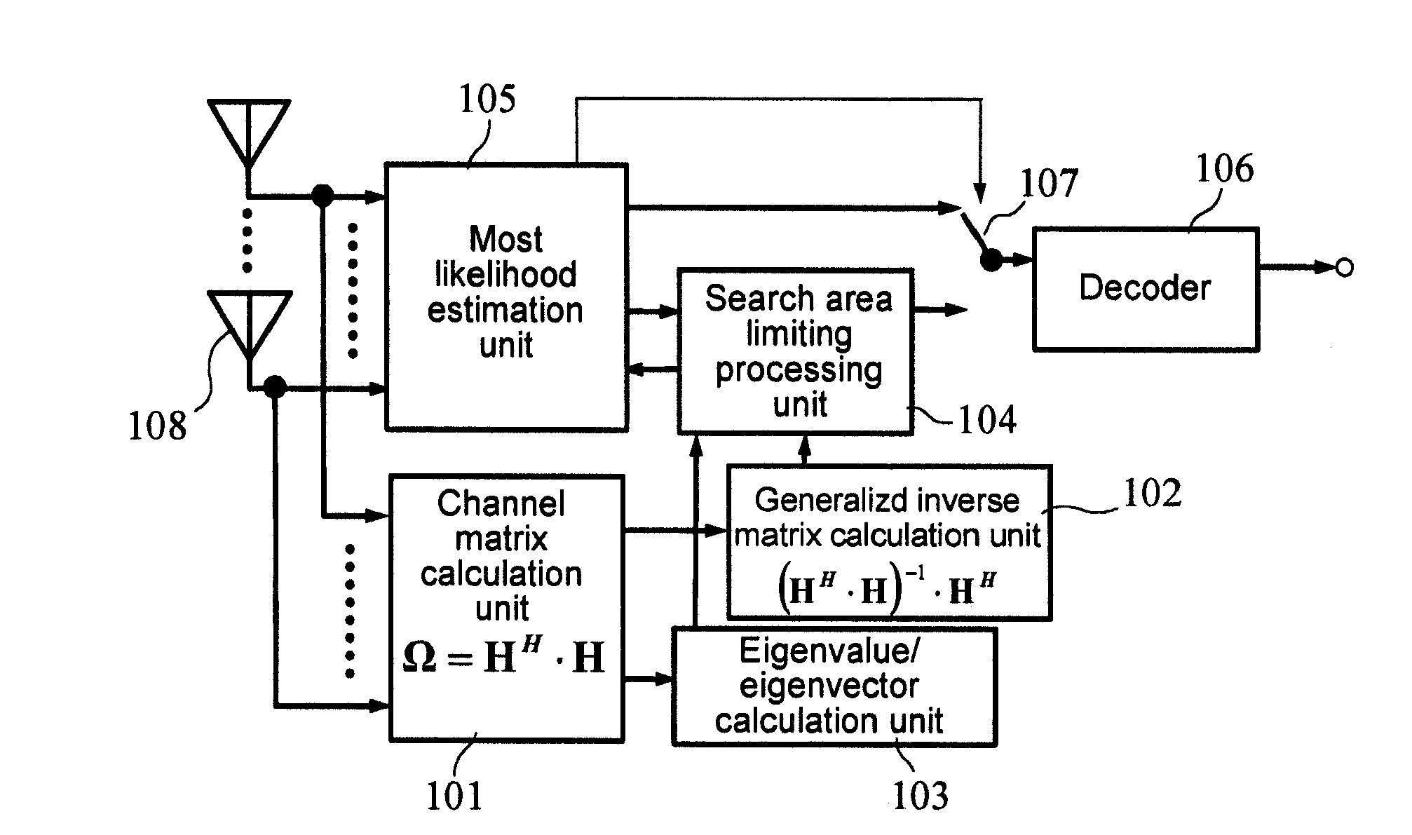
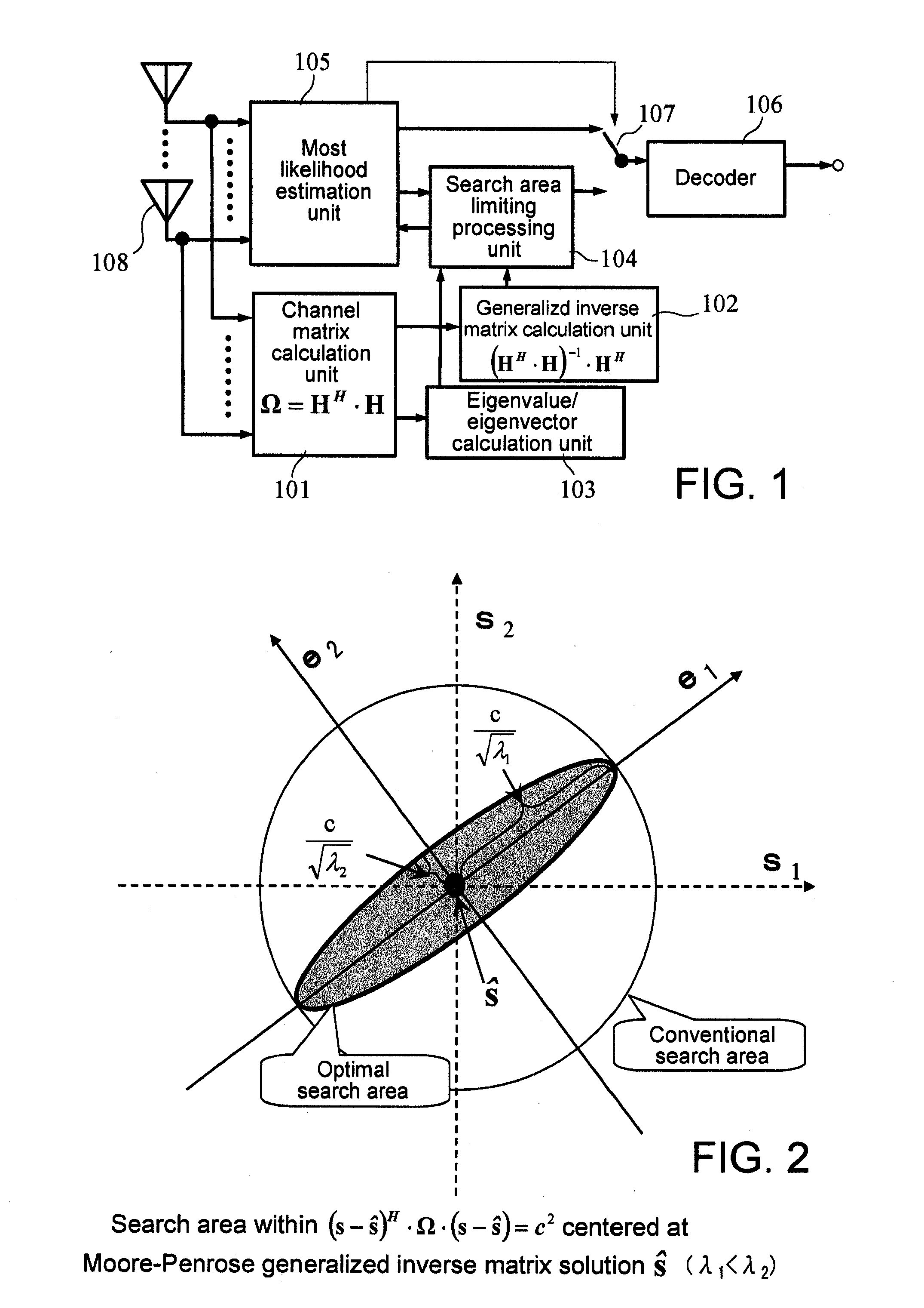
A MIMO decoder, which is capable of changing a search area of a transmission signal vector in accordance with a change in a channel matrix, includes: a generalized inverse vector matrix calculation unit for calculating a generalized inverse matrix of Moore-Penrose derived from a channel matrix indicative of a radiowave propagation environment; a search area limiting processing unit for performing weighting for each eigenvector calculated from the channel matrix in inverse proportion to a square root of an eigenvalue corresponding to the eigenvector, and determines the search area of the transmission signal vector centered at the generalized inverse matrix solution of Moore-Penrose based on the weighted result; and a most likelihood estimation unit for searching for a transmission signal vector by use of a most likelihood estimation based on the search area determined by the search area limiting processing unit.

Description

TECHNICAL FIELD[0001]The present invention relates to a most likelihood detecting method in a MIMO (Multiple-Input / Multiple-Output) space multiplex transmission used in mobile communications and the like, and more particularly, to a MIMO decoder and a MIMO decoding method which are suitable when a search area of a transmission signal vector changes in accordance with a channel matrix which changes due to variations in radiowave propagation environment and the like.BACKGROUND ART[0002]On radiowave propagation paths in mobile communications, radiowaves coming from a transmission antenna undergo reflections and dispersions in accordance with surrounding topologies and the like, and reach a receiver in an aggregation of elementary waves. Since respective elementary waves differ in propagation path length and phase from one another, the fading phenomenon occurs due to the arrival of such an aggregate of elementary waves which have undergone reflections and dispersions. The fading phenome...

Claims


Application Information

Patent Timeline
Patent Type & Authority Applications(United States)
IPC IPC(8): H04L27/06H04B7/02H04J99/00
CPCH04B7/0413H04B7/0854H04L25/03242H04L25/03114H04L25/0244
Inventor MARU, TSUGUO
Owner NEC CORP
Learn More