Spindle device of machine tool

a machine tool and spindle technology, applied in the direction of attachable milling devices, chucks, manufacturing tools, etc., can solve the problems of reducing suction efficiency, complicated structure, and inability to automatically change tools, so as to prevent the entry of outside air

Inactive Publication Date: 2009-11-12
DMG MORI SEIKI CO LTD
View PDF6 Cites 15 Cited by
  • Summary
  • Abstract
  • Description
  • Claims
  • Application Information

AI Technical Summary

Benefits of technology

[0015]According to the above embodiment, since the seal mechanism includes the elastic member bringing the seal member, which is slidably in contact with the outer peripheral surface of the rear end of the draw bar, into pressure contact with the step of the inner pipe, it is possible to constantly bring an end surface of the seal member into pressure contact with the step owing to an elastic force of the elastic member while bringing an inner peripheral surface of the seal member into slidable contact with the outer peripheral surface of the draw bar. This makes it possible to more surely prevent the entrance of outside air.

Problems solved by technology

The aforesaid conventional milling cutter has a problem that the structure is complicated since the suction hopper is attached to the clamping and supplying device, and automatic tool change is not possible due to a structural reason.
The structure having the suction hole may cause a problem of increasing the outside diameter of the draw bar, and as a result, increasing the inside diameter of the spindle compared with that in the conventional art, depending on the structure of the draw bar, and further, may lower suction efficiency because air is sucked from a portion connected to a drive mechanism reciprocatingly driving the draw bar.

Method used


Image

  • Spindle device of machine tool
  • Spindle device of machine tool
  • Spindle device of machine tool

Examples


Embodiment Construction

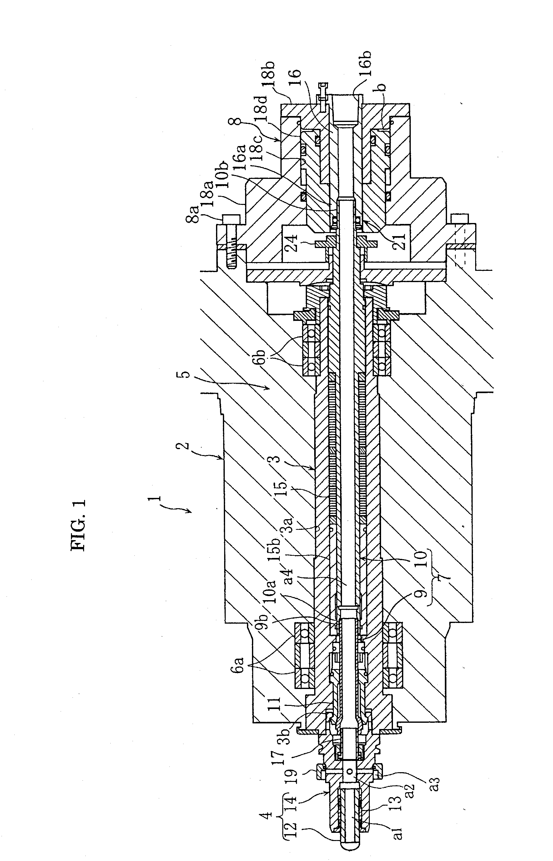
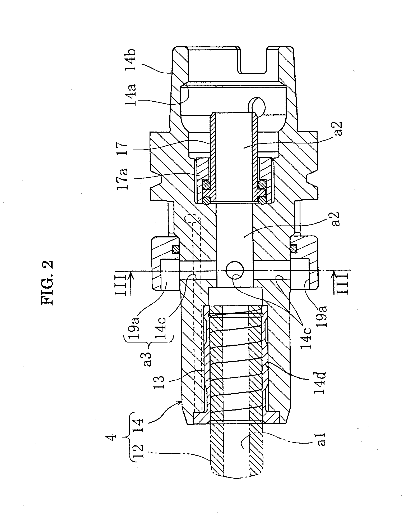
[0024]Hereinafter, an embodiment of the present invention will be described based on the accompanying drawings. FIG. 1 to FIG. 8 are views to explain a spindle device of a machine tool according to one embodiment of the present invention.

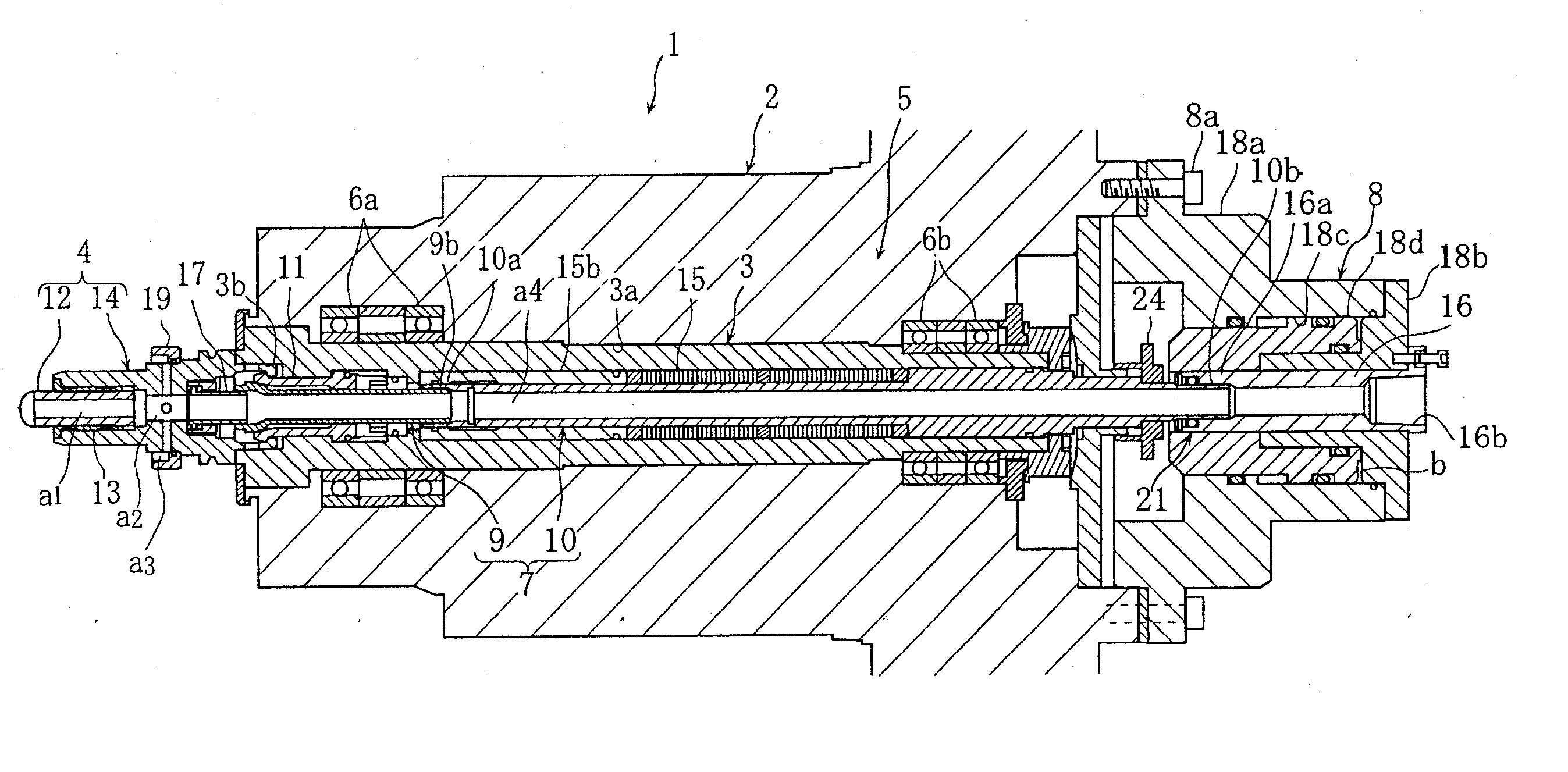
[0025]In the drawings, 1 denotes a spindle device included in a machine tool such as a vertical or horizontal machining center. The spindle device 1 has: a spindle head 2 supported by a column; a spindle 3 rotatably supported by the spindle head 2; a tool holder 4 supported by a tip portion of the spindle 3; and a clamping mechanism 5 clamping / unclamping the tool holder 4 to / from the spindle 3.

[0026]The spindle 3 is a cylinder having a through hole 3a in an axial center. A front portion and a rear portion of the spindle 3 are rotatably supported by the spindle head 2 via a front bearing 6a and a rear bearing 6b respectively. Further, a tapered hole 3b is formed in a front end portion of the through hole 3a of the spindle 3, and the tool holder 4 is ...


PUM

PropertyMeasurementUnit
pressureaaaaaaaaaa
diameteraaaaaaaaaa
suction efficiencyaaaaaaaaaa

Abstract

It is an object to provide a spindle device of a machine tool which has a simple structure and is capable of having high suction efficiency of cutting chips. A draw bar bringing engaging claws into engagement with a tool holder or releasing the engagement includes an engagement drive part moving the engaging claws to an engagement position with the tool holder; and a draw bar main body connected to the engagement drive part, and the engagement drive part is inserted into the draw bar main body to be detachably connected to an inner surface of the draw bar main body.

Description

BACKGROUND OF THE INVENTION[0001]1. Field of the Invention[0002]The present invention relates to a spindle device of a machine tool, and more particularly, to a spindle device capable of having improved efficiency in collecting cutting chips in dust form generated especially during the machining of light metal.[0003]2. Description of the Related Art[0004]As a milling cutter in which cutting chips in dust form generated during a cutting process of, for example, a magnesium alloy can be collected, there is one described in Japanese Patent Application Publication No. 2005-532917. This milling cutter has a suction opening formed in an axial core of a shank, and the suction opening communicates with a suction hopper attached to a clamping and supplying device.[0005]The aforesaid conventional milling cutter has a problem that the structure is complicated since the suction hopper is attached to the clamping and supplying device, and automatic tool change is not possible due to a structural...

Claims


Application Information

Patent Timeline
Patent Type & Authority Applications(United States)
IPC IPC(8): B23C5/26B23C1/00
CPCB23B31/02B23B31/265B23B2270/62B23Q1/0036Y10T408/50B23Q11/0046Y10T409/309464Y10T409/304088B23Q1/70
Inventor TADA, KEIGOHAYASHI, TOMOHIKO
Owner DMG MORI SEIKI CO LTD
Why Eureka
Try Eureka