
Process for the preparation of an artificial latex

a technology of artificial latex and process, which is applied in the field of preparation of conjugated diene polymer latex and isoprene rubber latex, can solve the problems of increasing maintenance costs, relatively unstable latex, and prone to coagulation

Active Publication Date: 2009-11-12
CARIFLEX PTE LTD
View PDF14 Cites 24 Cited by
  • Summary
  • Abstract
  • Description
  • Claims
  • Application Information

AI Technical Summary

Benefits of technology

[0024](d) latex concentration, forming an artificial latex with a higher solids content, characterized in that in step (b) a premix is formed first, which is subsequently homogenized into an oil-in-water emulsion, and wherein the premix is formed by mixing the cement with the aqueous soap solution at a volume ratio of 1:1.5 to 1:3 using at least one homogenizer comprising a stator and a rotor, that is operated at a tip speed of the outer ring of the rotor in the ra

Problems solved by technology

As indicated in this reference, experience has shown that latexes are relatively unstable and tend to coagulate when subjected to mechanical stress.
Mechanical instability may be brought about by the simple movement of an agitator stirring the colloid.
Maintenance costs are increased because the equipment becomes coated with the coagulated rubber and furthermore, an appreciable quantity of the rubber is lost.
Another type of instability encountered with polymer latexes is that they oil-out and develop coagulum during the solvent stripping step.
Moreover, the equipment to be used in this process is very hard to scale-up to commercial size,
On the other hand, it has been found that the molecular weight of isoprene rubber is reduced in this step, by mechanical degradation, which adversely affects the properties of the articles prepared there from.

Method used


Image

  • Process for the preparation of an artificial latex

Examples


example 1

[0046]A polymer cement was made by dissolving a high cis polyisoprene (MW of about 3 million, made by anionic polymerization) into a volatile hydrocarbon solvent. This was done at a solids content of about 10% wt. An aqueous soap solution was prepared using a rosin-type soap at a concentration of from about 1-2% wt.

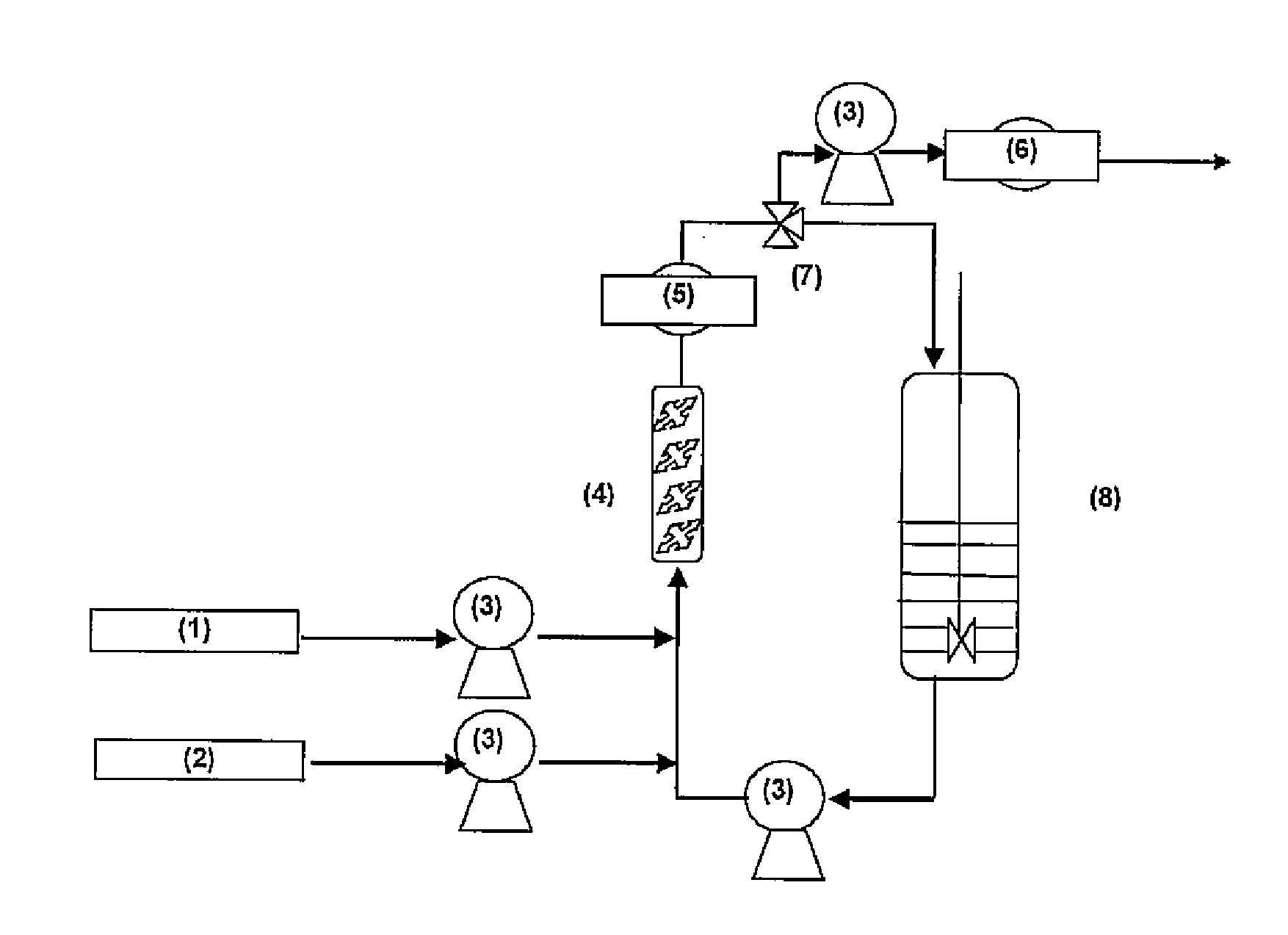
[0047]Experiments were carried out at 15-25° C. in an IR-latex emulsification unit consisting of a rotor / stator homogenizer (Cavitron CD1000 with conical rotor / stator system); a holding vessel (30 L glass double wall holding vessel equipped with a stirrer and inert gas system, max. pressure 1 bar g); a static mixer (120 cm length / 2.54 cm diameter, with 24 mixing elements); and Gear pumps for pumping cement, soap and emulsion together with weighing systems for metering the different flows.

[0048]The rotor / stator homogenizer (#1) was used at a tip speed varying from 9-14 / s. In addition, experiments were carried out within an experimental window wherein the cement / soap v / v ra...


PUM

PropertyMeasurementUnit
Lengthaaaaaaaaaa
Percent by massaaaaaaaaaa

Abstract

A process of producing an artificial latex, comprising the steps:(a) cement formation, wherein a rubber is dissolved in a suitable hydrocarbon solvent;(b) emulsification of the cement formed in step (a), together with an aqueous soap solution, thus forming an oil-in-water emulsion;(c) hydrocarbon solvent removal, resulting in a latex of the rubber having particles of a median particle size in the range of from about 0.5 to 2.0 μm, and optionally(d) latex concentration, forming an artificial latex with a higher solids content, characterized in that in step (b) a premix is formed first, which is subsequently homogenized into an oil-in-water emulsion, and wherein the premix is formed by mixing the cement with the aqueous soap solution at a volume ratio of 1:1.5 to 1:3 using at least one homogenizer comprising a stator and a rotor, that is operated at a tip speed of the outer ring of the rotor in the range of from 8 to 16 m / s, and wherein the premix is subsequently homogenized in a rotor / stator homogenizer operated at a tip speed of the outer ring of the rotor in the range of from 16 to 35 m / s.

Description

TECHNICAL FIELD[0001]The present invention concerns a process of producing an artificial latex, comprising a man-made emulsion of a rubber in water. More in particular, the invention concerns the preparation of a conjugated diene polymer latex, more specifically an isoprene rubber latex.BACKGROUND ART[0002]Both natural and synthetic rubber latexes are emulsions of rubber in water. The emulsions are stabilized with proteins or surface-active agents. The median diameter of rubber particles average varies from 0.5 to 2.0 micron. It may be as low as 0.1 micron for some synthetic latexes and tends to be nearly 1 micron for natural latex. The term “latex” is applied to synthetic as well as natural products, and stems from the botanical name of the milky fluid that is derived from rubber trees and which is the source of natural rubber. The term “serum” is used for the aqueous medium.[0003]Processes for producing artificial latexes have been known for many years. For instance, the process i...

Claims


Application Information

Patent Timeline
IPC IPC(8): C04B24/28
CPCC08J3/07Y10S516/925C08J2309/00C08J3/03C08J3/09C08C1/02C08J3/05
Inventor VAN DER HUIZEN, ADRIE A.SONDERMAN, MARC S.VAN DER WAAL, ARWIN W.DE JONG, WOUTERNICOLAI, ANTON
Owner CARIFLEX PTE LTD
Learn More