
Roller for fixing and image fixing apparatus using roller for fixing

a technology of fixing apparatus and roller, which is applied in the direction of electrographic process apparatus, instruments, optics, etc., can solve the problems of reducing function, reducing rubber elasticity, and reducing the elasticity of the fluororesin layer, so as to prevent wrinkles

Active Publication Date: 2009-11-19
CANON KK
View PDF4 Cites 16 Cited by
  • Summary
  • Abstract
  • Description
  • Claims
  • Application Information

AI Technical Summary

Benefits of technology

[0010]The present invention is achieved in view of the above described problems, and provides a roller for fixing that can prevent wrinkles from occurring on a surface of the roller during production, and an image fixing apparatus using the roller for fixing.

Problems solved by technology

However, a thermal insulation layer significantly expands in a process of calcining the liquid coated on the surface of the roller for fixing, and the expansion affects the liquid containing dispersed fluororesin via the thermal storage layer.
Then, even if the thermal insulation layer is cooled and shrinks after the calcining, the fluororesin layer remains separated (cracked) or wrinkled.
However, the fluororubber latex layer containing the dispersed high thermal conductive filler eventually has low rubber elasticity.
This reduces a function of the fluororubber latex of preventing cracks or wrinkles in a releasing layer, and causes wrinkles to easily occur on the surface during production.

Method used


Image

  • Roller for fixing and image fixing apparatus using roller for fixing
  • Roller for fixing and image fixing apparatus using roller for fixing
  • Roller for fixing and image fixing apparatus using roller for fixing

Examples


embodiment 1

[0023](1) Example of Image Forming Apparatus

[0024]FIG. 7 is a model view of a configuration of an example of an image forming apparatus including an image fixing apparatus according to the present invention. The image forming apparatus is a laser beam printer using an electrophotographic process.

[0025]In an image forming portion, a drum shaped electrophotographic photoreceptor (hereinafter referred to as a photosensitive drum) 51 as an image bearing member is rotated in an arrow direction at a predetermined circumferential velocity (process speed) based on a print signal. An outer peripheral surface (surface) of the photosensitive drum 51 is charged by a charger 52 to uniformly have a predetermined polarity and potential. Then, a laser scanner unit 53 writes image information on a charged surface on the surface of the photosensitive drum 51. The laser scanner unit 53 outputs laser light L modulated according to time-series electric digital pixel signals of image information input by...

embodiment 2

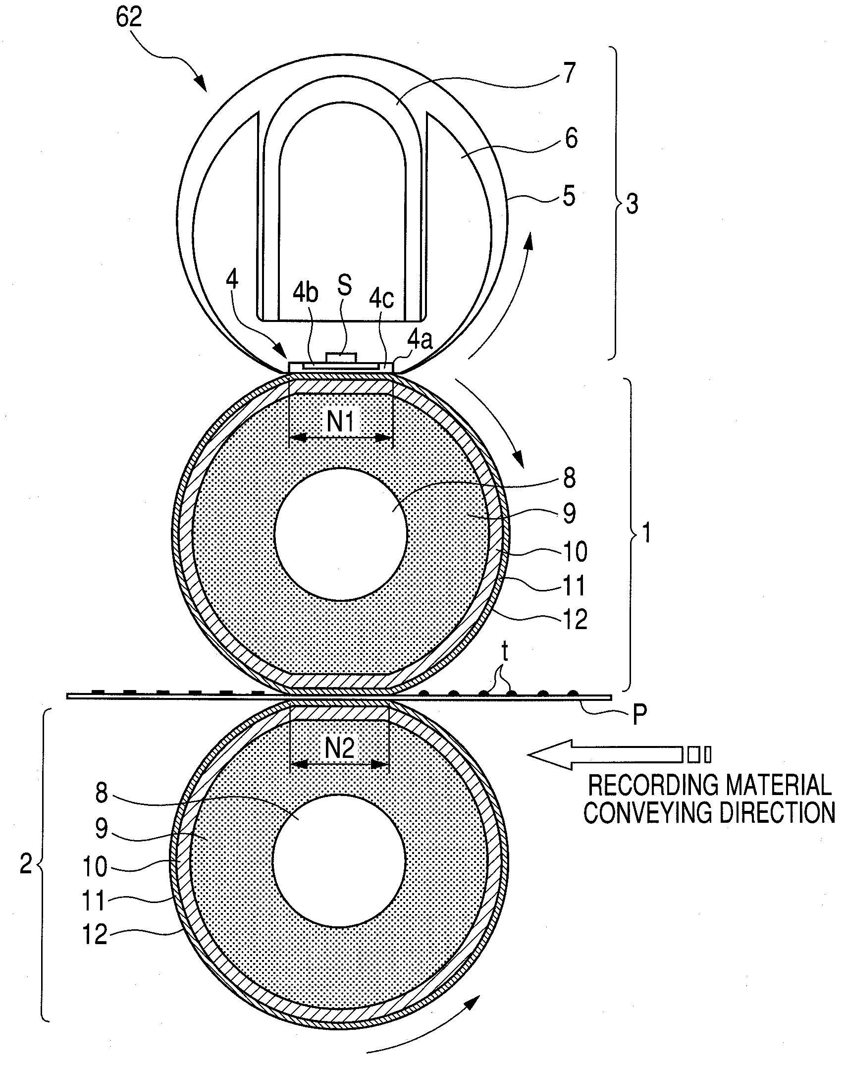
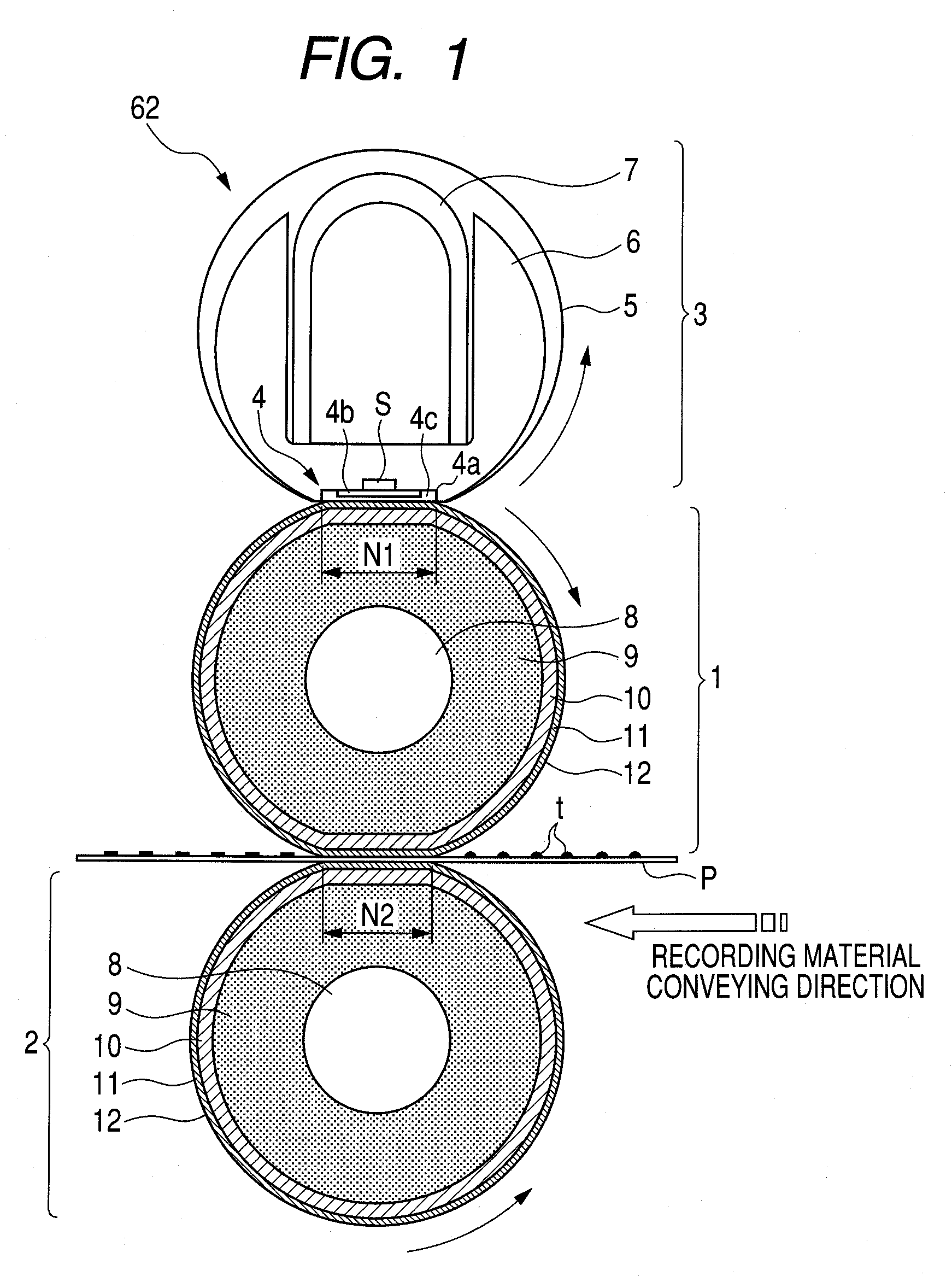
[0101]In Embodiment 1, the example in which the roller for fixing is used as the fixing roller and the pressure roller of the external heating roller type image fixing apparatus 62 is described. The roller for fixing is not limited thereto, but can be used as a pressure roller of a film heating type image fixing apparatus (see FIG. 6).

[0102]FIG. 6 is a cross sectional side model view of an example of a film heating type image fixing apparatus 62 using a roller for fixing as a pressure roller.

[0103]A film unit 71 includes a heater 72 as a heating source and a holder 73 supporting the heater 72. A sleeve-shaped flexible film (endless belt) 74 as a flexible member is externally loosely fitted to an outer periphery of the holder 73. A rigid stay 75 is provided on the holder 6 inside the film 74.

[0104]A pressure roller 2 is placed in parallel with the film unit 71, and opposite ends of a core metal 8 are rotatably held by an apparatus frame via a bearing (not shown). A predetermined pres...


PUM


Abstract

A roller for fixing and an image fixing apparatus using the roller for fixing that can prevent wrinkles from occurring on a roller surface. The roller for fixing includes at least an elastic layer on a core metal and includes a thermal conductive fluororubber latex layer containing a mixture of fluororubber, fluororesin and thermal conductive fillers more outer side than the elastic layer, wherein an intermediate layer made of silicone rubber having higher thermal conductivity than the thermal conductive fluororubber latex layer is provided between the thermal conductive fluororubber latex layer and the elastic layer, and the intermediate layer is configured so that an elastic parameter Y(=H×T) satisfies a relational expression:Y≧4200where H (degree) is Asker-C hardness of the silicone rubber having higher thermal conductivity (500 g load) and T (μm) is a thickness of the silicone rubber having higher thermal conductivity.

Description

BACKGROUND OF THE INVENTION[0001]1. Field of the Invention[0002]The present invention relates to a roller for fixing used in an image fixing apparatus included in an image forming apparatus such as an electrophotographic copying machine or an electrophotographic printer, and an image fixing apparatus using the roller for fixing.[0003]2. Description of the Related Art[0004]Electrophotographic copying machines and electrophotographic printers include an image fixing apparatus for heating and fixing, on a recording material, an unfixed toner image carried by the recording material.[0005]A roller for fixing such as a fixing roller or a pressure roller included in an image fixing apparatus needs a releasing layer for preventing adhesion of toner. A method of providing a releasing layer includes a method of covering a surface of a roller for fixing with tube-shaped fluororesin, or a method of coating a surface of a roller for fixing with a liquid containing dispersed fluororesin powder, a...

Claims


Application Information

Patent Timeline
Patent Type & Authority Applications(United States)
IPC IPC(8): G03G15/20
CPCG03G15/2053G03G2215/2051G03G2215/2019
Inventor OMATA, MASAHITOUMEHARA, SHOJIKISHINO, KAZUOMATSUNAKA, KATSUHISATOMOYUKI, YOJI
Owner CANON KK
Features
  • Generate Ideas
  • Intellectual Property
  • Life Sciences
  • Materials
  • Tech Scout
  • Unparalleled Data Quality
  • Higher Quality Content
  • 60% Fewer Hallucinations
Learn More