Optical Film, Method of Producing the Same and Image Displaying Apparatus Employing the Optical Film

a technology of optical film and method, applied in the direction of instruments, polarising elements, cellulosic plastic layered products, etc., can solve the problems of large-scale apparatus required to evaporate solvent, weak stripe defect of obtained film, and insufficient method to meet the requirement. , to achieve the effect of reducing the number of foreign substances

Inactive Publication Date: 2009-11-19
KONICA MINOLTA OPTO
View PDF8 Cites 50 Cited by
  • Summary
  • Abstract
  • Description
  • Claims
  • Application Information

AI Technical Summary

Benefits of technology

[0019]The present invention has been completed on the basis the above problems. An object of the present invention is to provide an optical film in

Problems solved by technology

However, no method has been sufficient to meet the requirement for the reduction of the number of foreign substances.
From the viewpoint of enhanced uniform film thickness, a norbornene-based polymer film or a cellulose triacetate film has been commonly employed, but there have been problems that, for example, a large-scale apparatus is required to evaporate the solvent.
Accordingly, since leveling of the film on a support is not easy, the obtained film tends to have a strong stripe defect so called a “die line”.
There has been a problem that a bright-dark stripe cau

Method used


Image

  • Optical Film, Method of Producing the Same and Image Displaying Apparatus Employing the Optical Film
  • Optical Film, Method of Producing the Same and Image Displaying Apparatus Employing the Optical Film
  • Optical Film, Method of Producing the Same and Image Displaying Apparatus Employing the Optical Film

Examples


example 1

[1369]

[Preparation of Optical Film 1]Cellulose acetate propionate (acetyl100mass partssubstitution degree of 1.95, propionylsubstitution degree of 0.7, numberaverage molecular weight of 75,000,dried at 140° C. for 5 hours, glasstransition temperature: Tg = 174° C.)Trimethylol propane tri benzoate10mass partsIRGANOX-1010 (produced by Ciba1mass partSpecialty Chemicals)

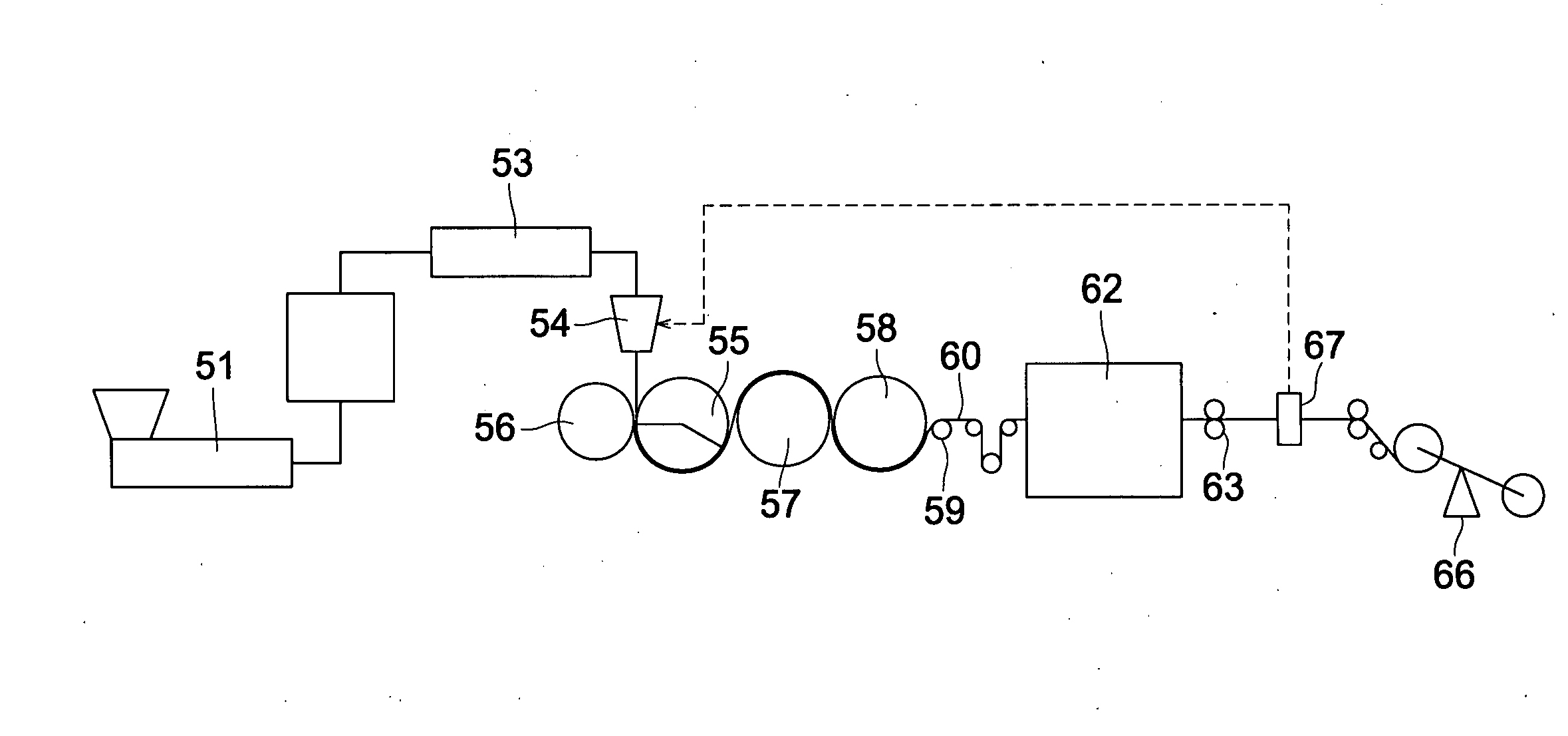
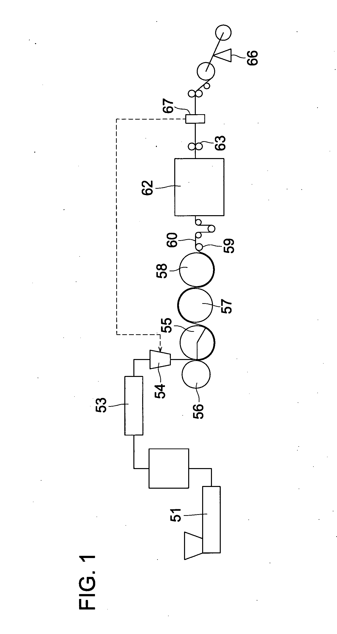
[1370]After mixing the above materials using a V-shaped mixer for 30 minutes, the materials were melted at 220° C. and cylindrical pellets of 4 mm in length and 3 mm in diameter were formed using twin screw extruder 51 (PCM30, produced by IKEGAI Corp.) shown in FIG. 1. At this time, nitrogen was added together with the material from extruder 51 inlet to reduce the oxygen concentration.

[1371]Subsequently, the pellets were supplied to single screw extruder 53 (GT-50, produced by Plastics Engineering Laboratory) having a diameter of 50 mm and equipped with casting die 54 to form a film.

[1372]The preset temperature of the si...

example 2

[1403]Optical films were prepared in the same manner as Example 1 except that the high refractive index layer and the low refractive index layer were not applied, whereby optical films each having a hard coat layer were obtained. When the number of foreign substances of these optical films was evaluated, the same results as Example 1 were obtained.

example 3

[1404]Optical films were prepared in the same manner as Example 1 except that, after the hard coat layer was subjected to a adhesion improving treatment, the low refractive index layer was applied without applying the high refractive index layer, whereby optical films each having a two layer structure of the hard coat layer and the low refractive index layer were obtained. When the number of foreign substances of these optical films was evaluated, the same results as Example 1 were obtained.


PUM

PropertyMeasurementUnit
Massaaaaaaaaaa
Fractionaaaaaaaaaa
Fractionaaaaaaaaaa

Abstract

A method for producing an optical film, characterized by extruding a melt containing a cellulose ester resin from a casting die to thereby form a long length cellulose ester film at a draw ratio of 5 to 30, slitting both sides of the long length cellulose ester film and winding the same in roll form, and while unrolling the long length cellulose ester film from the roll, carrying out continuous coating of the surface hereof with an optical function layer.

Description

TECHNICAL FIELD[0001]The present invention relates to an optical film, a method of producing the same and an image displaying apparatus employing the optical film.BACKGROUND ART[0002]Liquid crystal displays have been widely used as monitors due to their small footprint and low energy consumption features, compared to old-fashioned CRT displays, and have become common in application of TV sets. For such liquid crystal displays, various optical films such as polarizing films, retardation films, antireflection films, brightness enhancement films are used.[0003]Since, in an optical film employed in the viewer side surface of an image displaying apparatus, a foreign substance appears as an image defect, reduction of such a foreign substance has been heretofore investigated. For a large screen TV, reduction of the number of foreign substances of one order of magnitude or more is required compared to the number of foreign substances acceptable for personal computers or for small screen dis...

Claims


Application Information

Patent Timeline
IPC IPC(8): B29D11/00B32B27/06C08J7/043C08J7/046
CPCB29C39/148G02B5/3033B29C41/30B29C43/22B29C47/0021B29C47/0033B29C47/004B29C47/0066B29C47/34B29C47/8845B29C55/143B29C2793/0063B29C2947/92152B29C2947/92638B29C2947/92647B29C2947/92666B29C2947/92704B29C2947/92742B29C2947/92761B29C2947/92933B29K2001/00B29K2001/12B29K2995/0034B29L2011/00B29L2031/3475C08J5/18C08J7/045C08J7/047C08J2301/10B29C41/28B29C2948/92704B29C48/08B29C48/13B29C48/0011B29C48/0022B29C48/355B29C48/91B29C48/914B29C48/9155B29C2948/92152B29C2948/92638B29C2948/92647B29C2948/92666B29C2948/92742B29C2948/92761B29C2948/92933Y10T428/3188C08J7/0423C08J7/0427C08J7/043C08J7/046B29C59/04G02B5/30B32B23/08G02F1/1335
Inventor YAJIMA, TAKATOSHIYAJIMA, TAKATOSHIKUREMATSU, MASAYUKIMURAKAMI, TAKASHI
Owner KONICA MINOLTA OPTO
Why Eureka
Try Eureka