Electrode for radiofrequency tissue ablation

a radiofrequency tissue and electrode technology, applied in the field of electrosurgical units, can solve the problems of excessive ablation and carbonization of living tissue and blood around the electrode, adverse effect on patients, and carbonization of tissue around the electrode, so as to achieve convenient extension of the ablation necrosis region, minimize bleeding, and maximize economic

Active Publication Date: 2009-11-19
RF MEDICAL
View PDF10 Cites 60 Cited by
  • Summary
  • Abstract
  • Description
  • Claims
  • Application Information

AI Technical Summary

Benefits of technology

[0018]According to the present invention, since cooling in the hollow electrode can be maximized economically and the saline solution can be discharged at a fixed flow rate to the inside of the living tissue which is in contact with the hollow electrode, it is possible to easily extend an ablation necrosis region of the living tissue.
[0019]In addition, the electrode can minimize bleeding, and can be easily applied to a doctor's operation.

Problems solved by technology

However, this technique has a problem in that the living tissue and blood around the electrode are excessively ablated and carbonized, and the carbonized living tissue around the electrode operates as an insulator which prevents extension of an ablation region of the living tissue.
However, when a flow rate of the saline solution which can be infused into the living tissue increases, it has a detrimental effect on a patient.
Therefore, since the flow rate of the saline solution which can be infused into the living tissue is restricted, if RF energy applied to the living tissue exceeds a limit point, carbonization of the tissue occurs around the electrode.
As a result, this method also has a limit in extending an ablation region.
However, if RF energy applied to the living tissue exceeds a limit point, carbonization of the tissue occurs around the electrode.
Consequently, this method also has a limit in extending the ablation region.
However, since it is difficult to couple the separate flow control means to the hollow electrode, there is an economical disadvantage.
Moreover, the sheath tube may reduce a cooling effect of the pressurized saline solution.
Further, since a diameter of the overall electrode, i.e. a thickness of a needle increases, when the electrode is inserted into the body, it causes severe bleeding.

Method used


Image

  • Electrode for radiofrequency tissue ablation
  • Electrode for radiofrequency tissue ablation
  • Electrode for radiofrequency tissue ablation

Examples


embodiments

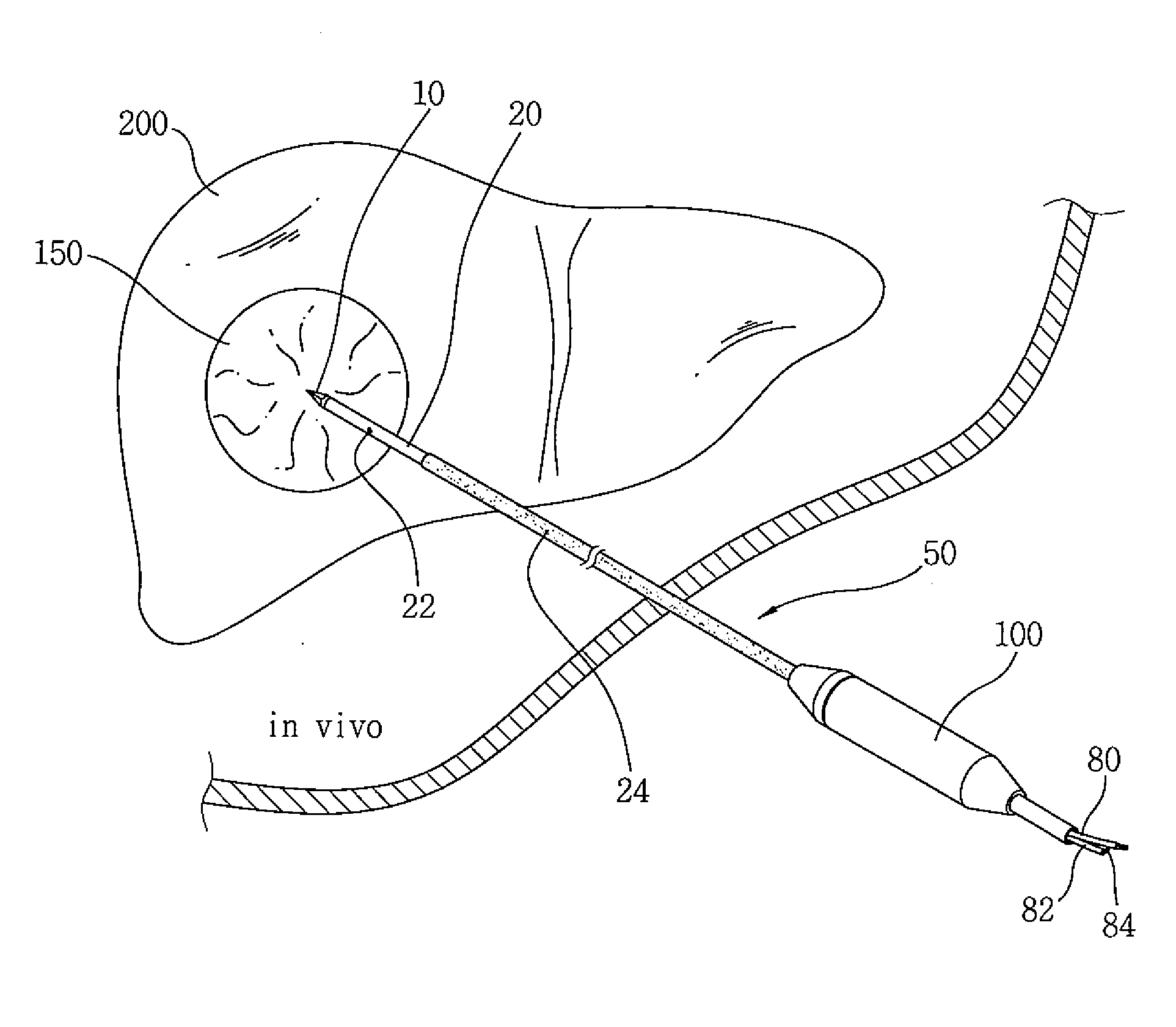
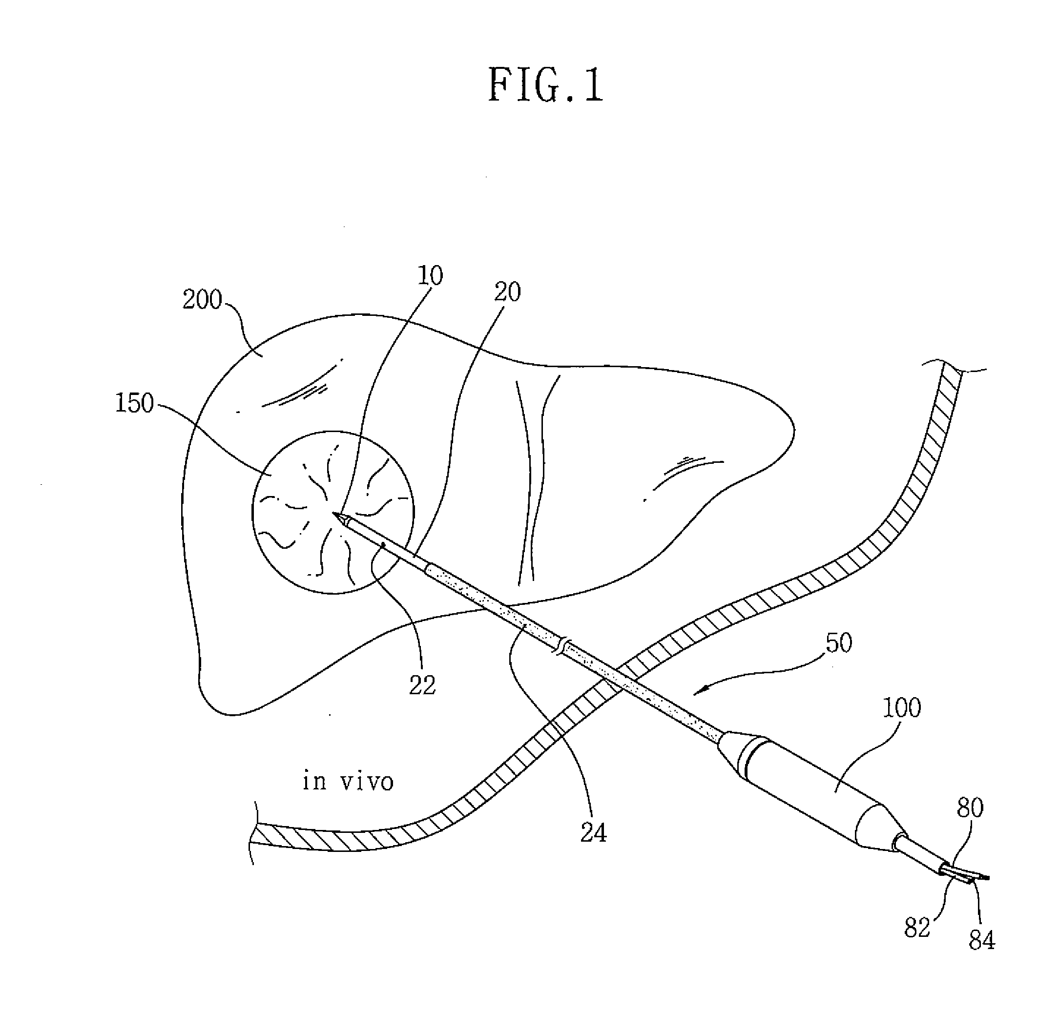
[0042]An experiment object was a cow's liver, and an RF generator was a product of Valleylab. In these experiments, the saline solution discharge holes 22 were provided in the hollow electrode 50, spaced apart from each other at 180°. Experiment results of Embodiments 1 to 7 changing the size of the holes 22 were shown in the following Tables 1 to 3.

TABLE 1TotalHolecirculationTotalradiusHoleflowhole areaEmbodiments(mm)numberrate(mm2)10.01290 cc / min0.00062820.0125290 cc / min0.000981330.015290 cc / min0.00141340.0175290 cc / min0.001923350.02290 cc / min0.00251260.0225290 cc / min0.003179370.025290 cc / min0.003925

[0043]‘Hole radius’ represents the radius of each hole 22 bored by the laser. As described above, the holes 22 were formed in positions spaced apart from each other at 180°. The area of the two holes 22 and the total circulation flow rate of the pressurized saline solution were as shown in the above Table 1.

TABLE 2Ratio of leakageRatio of dischargeflow rate to totalflow rate to totalDi...


PUM


Abstract

The present invention relates to an electrode for an electrosurgical unit for the use in ablating and necrosing a living tissue by RF electric energy. The present invention provides an electrode for an electrosurgical unit, including: a hollow electrode formed in an elongated hollow tube shape, a non-insulating region of a predetermined length being formed on one side of which, an insulating region being formed on an outer surface of which other than the non-insulating region; a saline solution circulation structure that supplies pressurized saline solution for cooling a living tissue which is in contact with the hollow electrode from the outside of the living tissue to the inside of the hollow electrode, and discharges the pressurized saline solution from the inside of the hollow electrode to the outside of the living tissue; and one or more saline solution discharge holes formed in the non-insulating region of the hollow electrode to discharge some of the circulating pressurized saline solution to the living tissue which is in contact with the hollow electrode.

Description

BACKGROUND OF THE INVENTION[0001]1. Field of the Invention[0002]The present invention relates to an electrode for an electrosurgical unit, and more particularly to, an electrode for an electrosurgical unit for the use in ablating and necrosing a living tissue by RF electric energy.[0003]2. Description of the Related Art[0004]A technique for piercing and inserting a long hollow tube-shaped electrode into a target living tissue and ablating (or coagulating) the living tissue by RF energy has been publicly known. In this case, when a current flows into the living tissue, the living tissue is heated, so that the living tissue and blood vessels are ablated by a more or less complicated biochemical mechanism. Such a process depends on ablation of a cell caused by thermal deformation of proteins in the cell over about 60° C. Here, the cell includes the tissue, blood vessel and blood. However, this technique has a problem in that the living tissue and blood around the electrode are excessiv...

Claims


Application Information

Patent Timeline
Patent Type & Authority Applications(United States)
IPC IPC(8): A61B18/18A61F7/00
CPCA61B18/1477A61B18/16A61B2018/00029A61B2218/002A61B2018/1253A61B2018/1425A61B2018/00083A61B18/12A61B18/14
Inventor JUN, MYONG-KI
Owner RF MEDICAL
Why Eureka
Try Eureka