Particle beam therapy system

Active Publication Date: 2009-11-26
HITACHI LTD
View PDF11 Cites 122 Cited by
  • Summary
  • Abstract
  • Description
  • Claims
  • Application Information

AI Technical Summary

Benefits of technology

[0017]According to the present invention, since a space in which the bending magnet included in the beam tran

Problems solved by technology

It is, however, difficult to reduce a time for blocking a beam in order to prevent the beam from being extracted from the accelerator in the conventional technique described in JP-A-2005-332794.
This is because an exciting

Method used


Image

  • Particle beam therapy system
  • Particle beam therapy system
  • Particle beam therapy system

Examples


first embodiment

[0029]The configuration and operations of a particle beam therapy system according to a first embodiment of the present invention are described below with reference to FIGS. 1 to 4F.

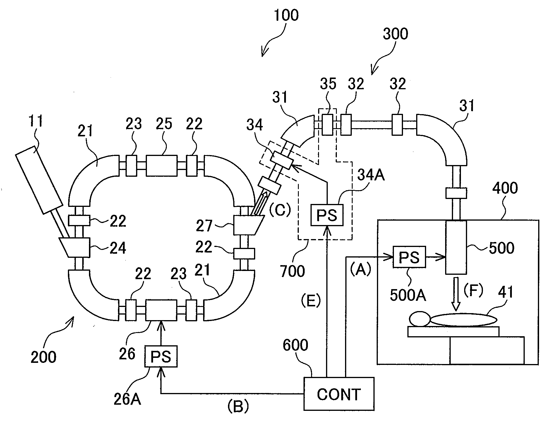
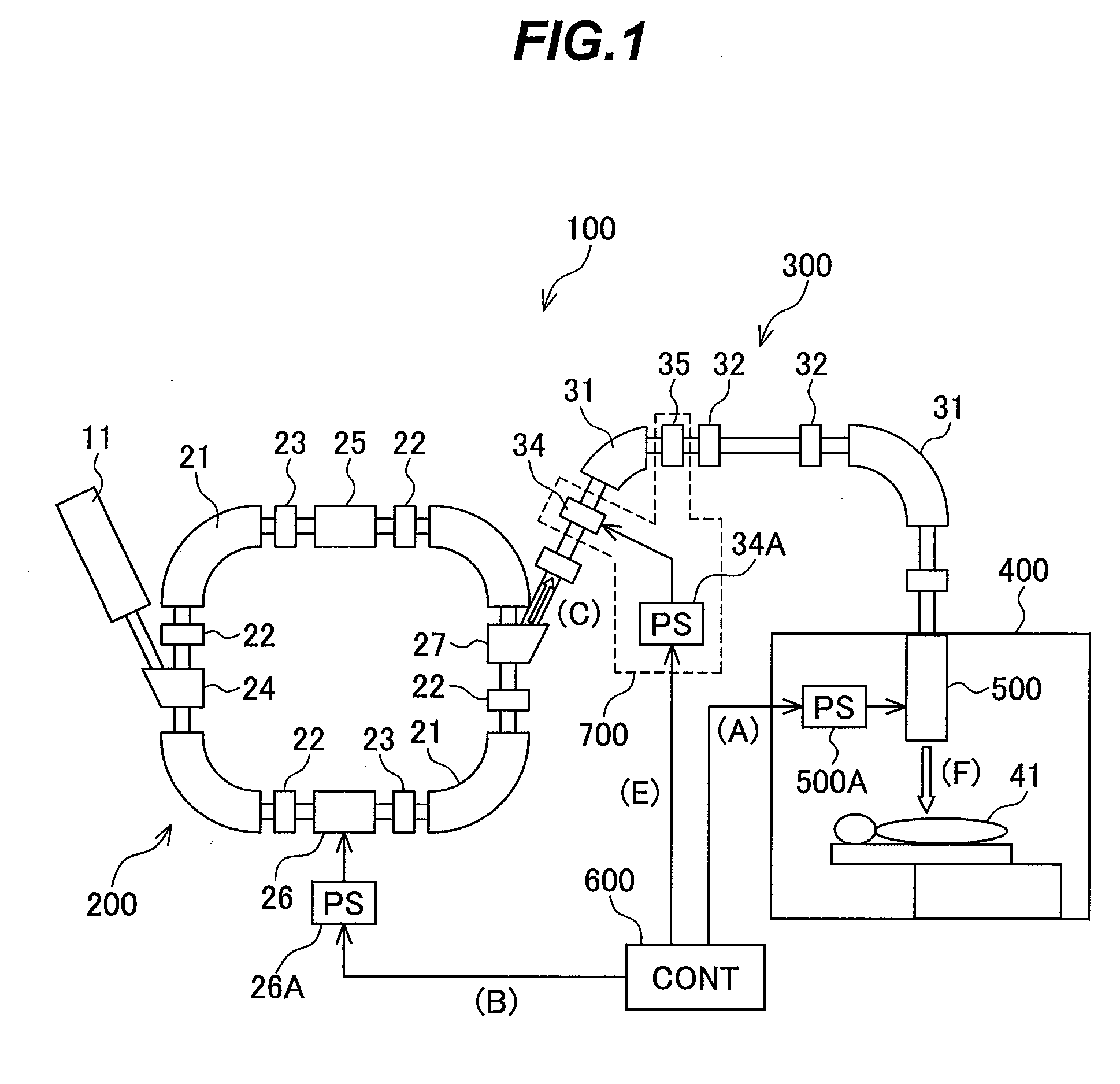
[0030]First, a description will be made of the entire configuration of the particle beam therapy system according to the first embodiment and the principle of irradiation with a particle beam with reference to FIGS. 1 to 3B. FIG. 1 is a diagram showing the configuration of the particle beam therapy system according to the first embodiment.

[0031]In FIG. 1, reference numeral 100 denotes the particle beam therapy system. The particle beam therapy system 100 includes a synchrotron 200, a beam transport system 300, an irradiation device 500 and a controller 600. The synchrotron 200 is adapted to accelerate a charged particle beam pre-accelerated by a pre-accelerator 11 such as a linac such that the charged particle beam has a predetermined energy level and then to output the charged particle beam. The beam tr...

second embodiment

[0053]Next, a description is made of the configuration and operations of a particle beam therapy system according to a second embodiment of the present invention. In the second embodiment, only parts different from the configuration and operations of the particle beam therapy system according to the first embodiment are described below.

[0054]FIG. 5 is a diagram showing the entire configuration of the particle beam therapy system 100A according to the second embodiment.

[0055]The particle beam therapy system 100A has a beam interrupting device 700A. The beam interrupting device 700A includes the beam shielding magnet 34, the exciting power supply 34A, a quadrupole magnet 36 and the beam dump 35. The exciting power supply 34 is adapted to excite the beam shielding magnet 34. The beam dump 35 is adapted to discard a beam component removed from the charged particle beam by the beam shielding magnet 34. The beam shielding magnet 34, the quadrupole magnet 36, the bending magnet 31, the bea...

third embodiment

[0060]The entire configuration and operations of a particle beam therapy system 100B according to a third embodiment of the present invention are described below. In the third embodiment, only parts different from the first embodiment are described.

[0061]FIG. 8 is a diagram showing the configuration of the particle beam therapy system 100B according to the third embodiment. The particle beam therapy system 100B according to the third embodiment uses a cyclotron 800 as an accelerator for accelerating a charged particle beam. The cyclotron 800 includes an ion source 81, an accelerating cavity 82, a bending magnet 83 and an extraction deflecting magnet 84. The ion source 81 is adapted to generate a charged particle beam. The accelerating cavity 82 is adapted to accelerate the charged particle beam for each circular movement of the beam. The bending magnet 83 is adapted to bend the charged particle beam to cause the beam to spirally circle around the cyclotron 800. The extraction deflec...


PUM


Abstract

A particle beam therapy system that is capable of irradiating a target area with an irradiation beam suitable for a particle beam therapy using a spot scanning method includes a synchrotron, a beam transport system and an irradiation device. The beam transport system is provided with a beam interrupting device adapted to block supply of a charged particle beam to the irradiation device. The beam interrupting device has a beam shielding magnet, an exciting power supply for the beam shielding magnet and a beam dump. The beam transport system has a bending magnet. The beam shielding magnet is provided on an inlet side of the bending magnet. The beam dump is provided on an outlet side of the bending magnet. A controller controls the exciting power supply to control the timing of an operation of the beam shielding magnet.

Description

BACKGROUND OF THE INVENTION[0001]1. Field of the Invention[0002]The present invention relates to a particle beam therapy system capable of high precision irradiation for treatment, and more particularly to a particle beam therapy system suitable for using a spot scanning irradiation method.[0003]2. Description of the Related Art[0004]In the recent aging society, a typical one of radiation therapies has attracted attention as one of cancer treatments since the radiation therapy is noninvasive to and has a low impact on human bodies. In addition, after the radiation therapy, the quality of life is highly maintained. Among the radiation therapies, a particle beam therapy system is a promising approach since the system provides an excellent dose concentration for an affected area of a patient. The particle beam therapy system uses a proton or a charged particle beam such as carbon, which is accelerated by an accelerator. The particle beam therapy system includes an accelerator, a beam t...

Claims


Application Information

Patent Timeline
IPC IPC(8): H01J3/14G21G5/00
CPCH05H7/12H05H7/04
Inventor SAITO, KAZUYOSHI
Owner HITACHI LTD
Why Eureka
Try Eureka