Laser microscope apparatus

a microscope and laser technology, applied in the field of laser microscope equipment, can solve the problems of difficult to achieve in the same microscope apparatus, inefficient utilization of energy of two pulsed laser beams, etc., and achieve the effect of low pri

Active Publication Date: 2009-11-26
EVIDENT CORP
View PDF7 Cites 14 Cited by
  • Summary
  • Abstract
  • Description
  • Claims
  • Application Information

AI Technical Summary

Benefits of technology

[0019]By so doing, by adjusting the timing between two pulsed laser beams on the surface of the specimen, the timings of two pulsed laser beams can be adjusted to correspond to the specific molecular vibration frequency in the specimen. By so doing, coherent anti-Stokes Raman scattering light can be efficiently generated. In addition, since the frequency difference can be arbitrarily adjusted, the frequency difference can also correspond to the vibration frequency of another molecule in the specimen.
[0020]In the laser microscope apparatus according to this invention, the frequency converter may also be a photonic crystal fiber. By using a photonic crystal fiber as the frequency converter, pulsed laser beams having broad frequency spectral bands with a given frequency dispersion can be readily obtained at low price. In addition, by selecting the type of the photonic crystal fiber to use, pulsed laser beams having various frequency spectral components and bands can be obtained. For this reason, the frequency difference between two pulsed laser beams can be adjusted to correspond to various vibration frequencies of molecules in the specimen.

Problems solved by technology

As a result, energies of two pulsed laser beams can not be efficiently utilized for the generation of coherent anti-Stokes Raman scattering light from the specific molecular vibration.
From the above reasons, the both observation methods with the coherent anti-Stokes Raman scattering microscope and the multiphoton excitation type laser microscope are different in the spec of pulsed laser beams to be used, and thus are difficult to achieve in a same microscope apparatus.

Method used


Image

  • Laser microscope apparatus
  • Laser microscope apparatus
  • Laser microscope apparatus

Examples


Embodiment Construction

[0029]Hereunder is a description of a laser microscope apparatus 1 according to one embodiment of the present invention, with reference to FIG. 1 to FIG. 4.

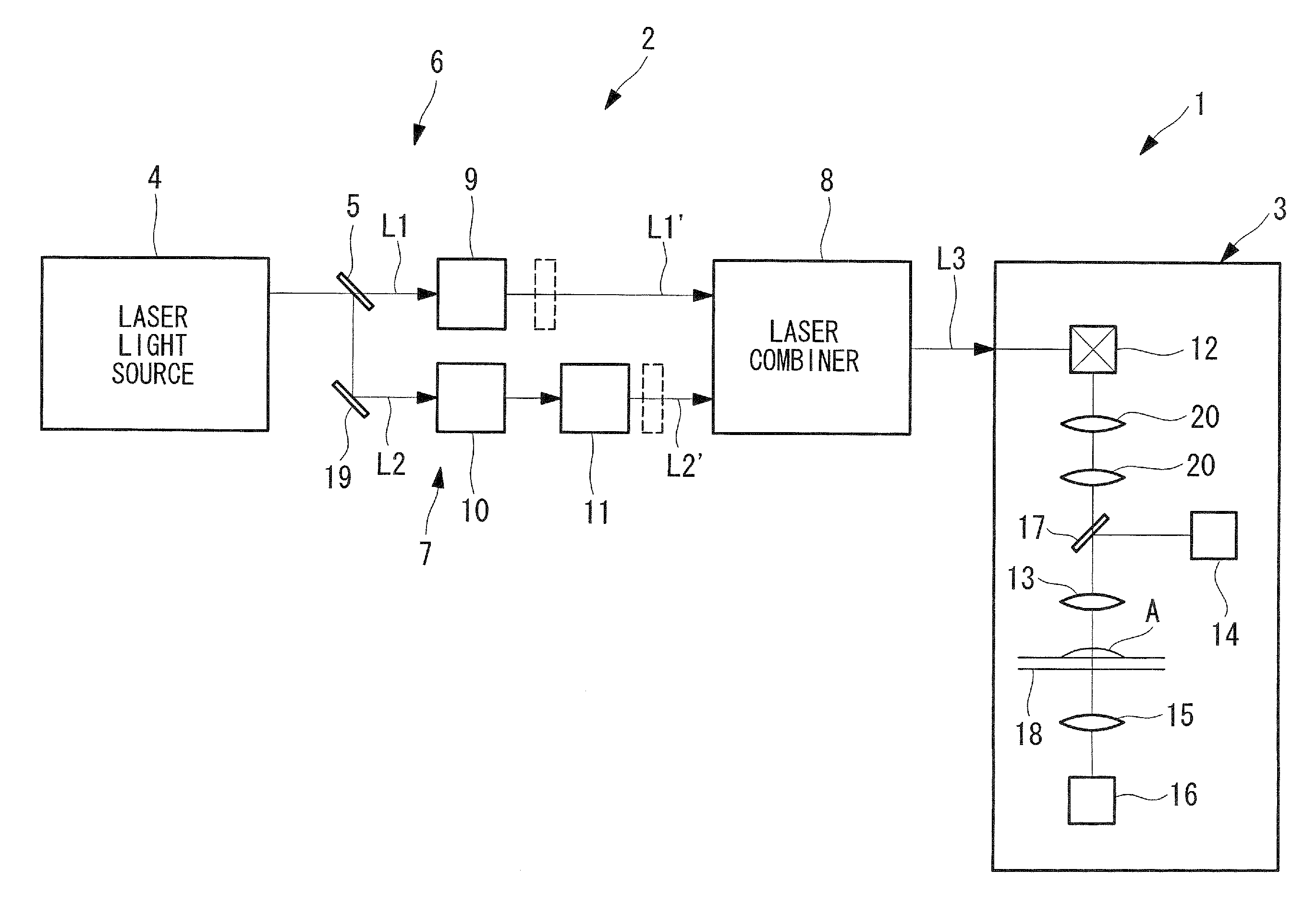
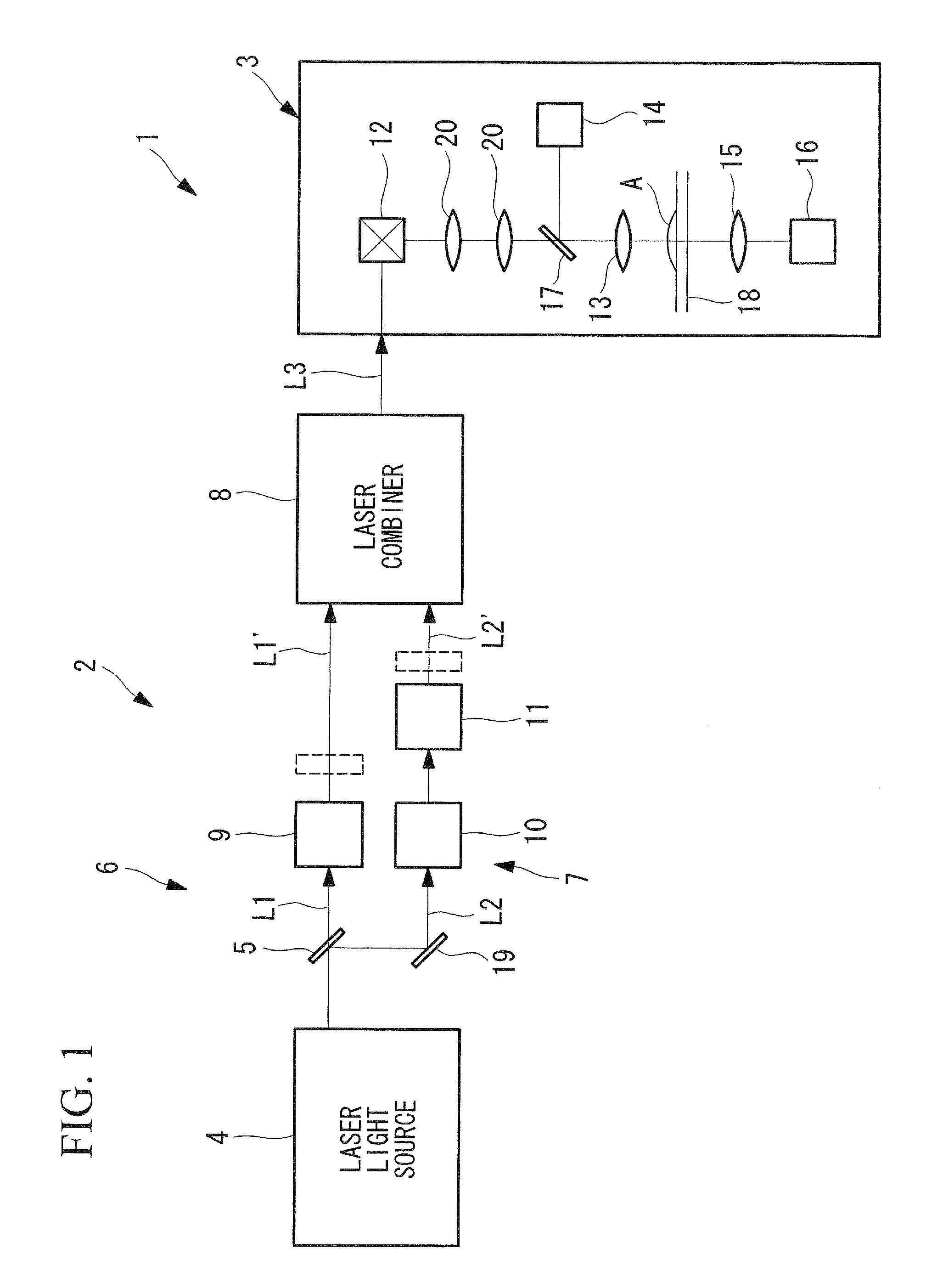
[0030]As shown in FIG. 1, the laser microscope apparatus 1 according to this embodiment comprises a laser light source device 2, and a microscope mainbody 3 for observing a specimen A by irradiation of laser beams from the laser light source device 2 onto the specimen A.

[0031]The laser light source device 2 comprises a single laser light source 4 which emits a femtosecond pulsed laser beam, a beam splitter (branching section) 5 which splits the femtosecond pulsed laser beam emitted from the laser light source 4 into two beams, two optical paths 6 and 7 through which the two femtosecond pulsed laser beams L1 and L2 that have been split by the beam splitter 5 are respectively transmitted, and a laser combiner 8 which combines two pulsed laser beams L1′ and L2′ that have been transmitted through these two optical paths 6 and 7.

[0032...


PUM


Abstract

To enable both observations of coherent anti-Stokes Raman scattering light and multiphoton fluorescence in a same apparatus so as to observe a specimen by various observation methods. There is provided a laser microscope apparatus comprising: two optical paths for guiding pulsed laser beams having two different frequencies whose frequency difference is approximately equal to a specific molecular vibration frequency in a specimen; a multiplexer for combining the pulsed laser beams guided through these two optical paths; and a frequency dispersion adjuster which is provided on at least one of these two optical paths, and is capable of adjustment to approximately equalize frequency dispersion quantities of the pulsed laser beams guided through the two optical paths.

Description

BACKGROUND OF THE INVENTION[0001]1. Field of the Invention[0002]The present invention relates to a laser microscope apparatus.[0003]This application is based on Japanese Patent Application No. 2008-135523, the content of which is incorporated herein by reference.[0004]2. Description of Related Art[0005]There is a known coherent anti-Stokes Raman scattering microscope with which a specimen is observed through generation and detection of coherent anti-Stokes Raman scattering light from a molecule in the specimen utilizing its specific molecular vibration (for example, refer to Japanese Unexamined Patent Application, Publication No. 2002-520612). Since this coherent anti-Stokes Raman scattering microscope utilizes a specific molecular vibration in the specimen, there is no need to previously label the observation target with a fluorescence probe likewise of a fluorescence microscope. In addition, the molecule for observation can be changed by changing the vibration to use.[0006]Convent...

Claims


Application Information

Patent Timeline
Patent Type & Authority Applications(United States)
IPC IPC(8): G01J3/44
CPCG01N21/6458G01N2021/656G01N2021/653G01N21/65
Inventor TAKIMOTO, SHINICHIHASHIMOTO, TAKESHIKUBO, HIROKAZUNAKATA, TATSUO
Owner EVIDENT CORP
Why Eureka
Try Eureka