Signal transmission apparatus and signal transmission method

a signal transmission apparatus and signal transmission technology, applied in the field of signal transmission, can solve the problems of complicated construction of synchronization processing, and insufficient transmission rate for super-high definition image signals

Active Publication Date: 2009-11-26
SONY CORP
View PDF6 Cites 28 Cited by
  • Summary
  • Abstract
  • Description
  • Claims
  • Application Information

AI Technical Summary

Benefits of technology

[0036]According to an embodiment of the present invention, it is possible to multiplex a multi-channel audio signal onto a transfer data stream. In addition, mapping is carried out so that the phase relationship between an image signal and an audio signal on a channel to which the audio signal is added is substantially the same phase relationship as that between the original input image signal and the input audio signal. As a result, the synchronization relationship between the image signal and the audio signal is maintained, a process that maintains the same synchronization phase across a plurality of channels is not required, and the construction for synchronization processing is simplified.

Problems solved by technology

However, with the present transfer technology, since only transfer at a bit rate of a maximum of around 10Gbps is possible on one channel even with a transfer method that uses optical fiber, which has the highest transfer rate, as the transfer path, the transfer rate is insufficient for a super-high definition image signal, and it is necessary to divide a super-high definition image signal into a plurality of channels to be transferred.
However, to transfer the 96 kHz audio on a maximum of 24 channels described above in synchronization with image data that has been divided between multiple channels, there is the problem that some kind of synchronization processing is required and that the construction for doing so becomes complicated.
The horizontal ancillary data space of CH1 alone is insufficient for the audio data that can be transferred using Mode C or Mode D.
However, with Mode C or Mode D where the 4096 / 24P / 4:4:4 / 12-bit signal is converted to a 3840 / 24P / 4:4:4 / 12-bit signal, it is not possible to transfer sixteen channels of 96 kHz audio.

Method used


Image

  • Signal transmission apparatus and signal transmission method
  • Signal transmission apparatus and signal transmission method
  • Signal transmission apparatus and signal transmission method

Examples


first embodiment

[0065]the present invention will now be described with reference to FIGS. 6 to 19.

[0066]FIG. 6 is a diagram showing the overall construction of an image transfer system for television broadcasting according to an embodiment of the present invention. This image transfer system is constructed of a plurality of broadcasting cameras 1 and a CCU (camera control unit) 2, with the respective broadcasting cameras 1 being connected to the CCU 2 by fiber optic cables 3.

[0067]The broadcasting cameras 1 have the same construction, and each functions as a signal transmitting apparatus that generates and transmits, as a 4 k×2 k signal (a super-high resolution signal with 4 k samples on 2 k lines), a 4096×2160 / 24P / 4:4:4 / 12-bit signal for Digital Cinema.

[0068]The CCU 2 is a unit that controls the broadcasting cameras 1, receives image signals from the respective broadcasting cameras 1, and transmits an image signal (“return video”) for displaying images being picked up by another broadcasting camer...

second embodiment

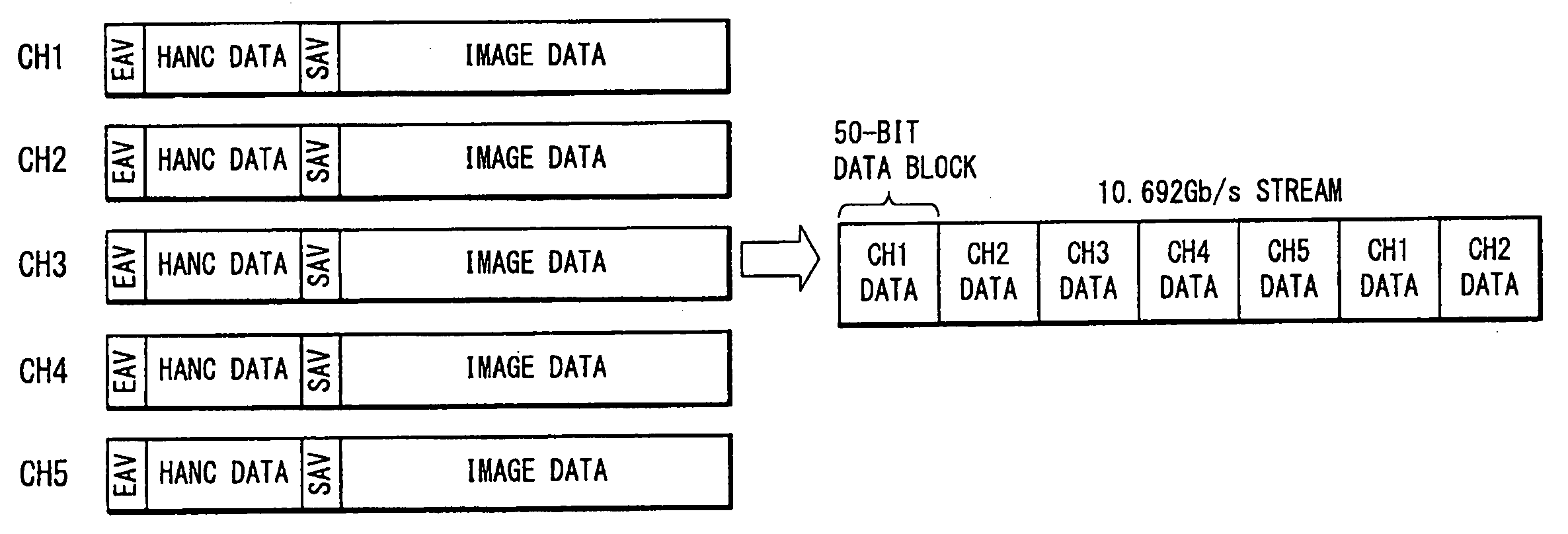
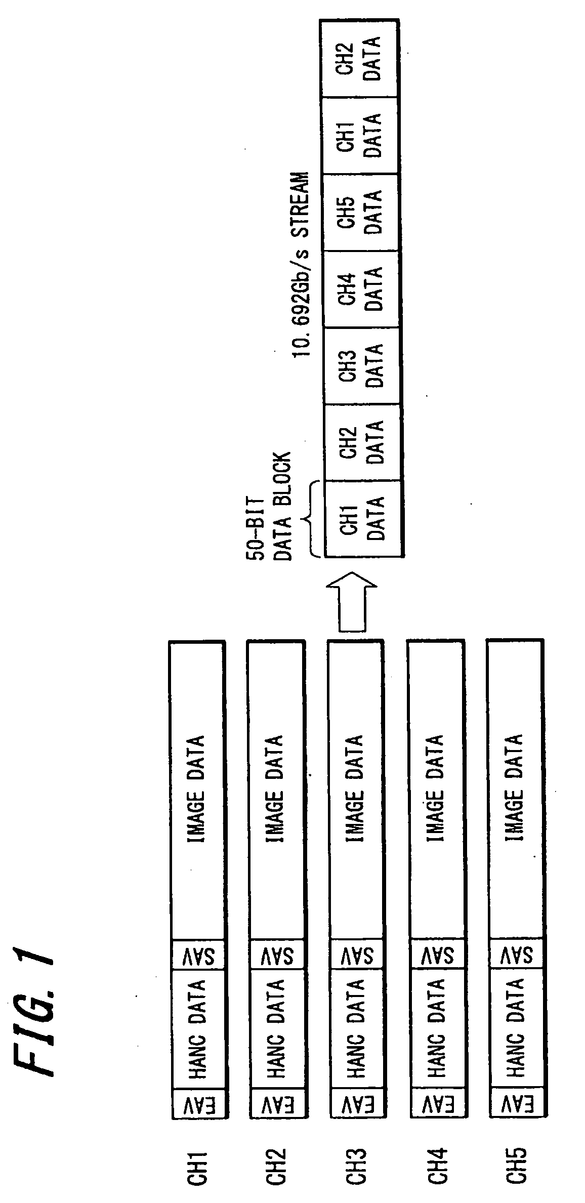
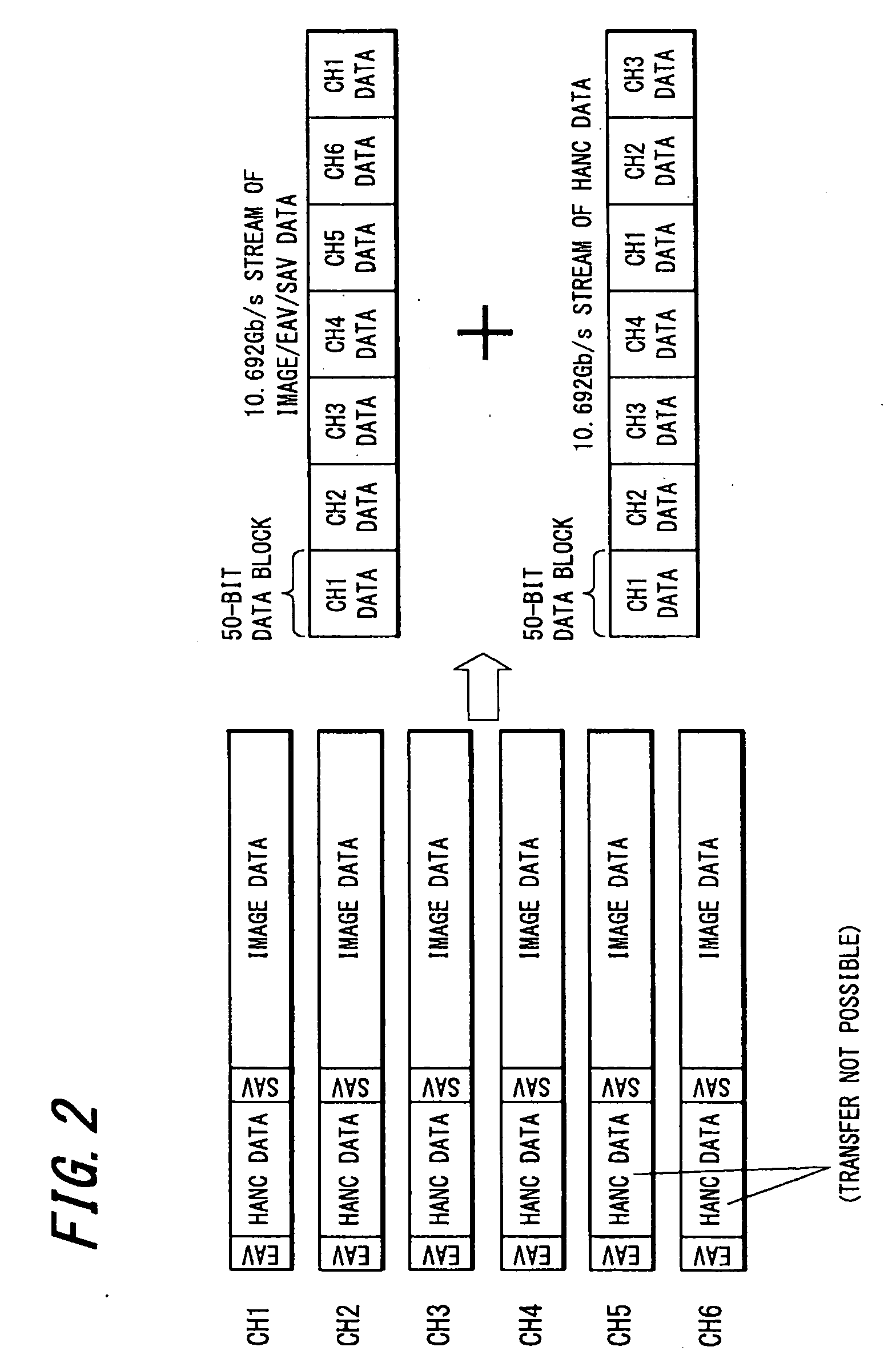
[0172]Next, an example operation of the mapping unit 11 according to the present invention will be described with reference to FIGS. 20 to 28.

[0173]Here, a method of multiplexing 3840×2160 / 24 / 1.001P, 24P, 25P, 30 / 1.001P, 30P / 4:2:2 or 4:4:4 / 10-bit, 12-bit pixel samples using Mode D defined by SMPTE 435 will be described.

[0174]FIG. 20 is a block diagram showing a signal transmitting apparatus 31 that relates to the present embodiment out of the circuit construction of the broadcasting camera 1. A 3840×2160 / 24 / 1.001P, 24P, 25P, 30 / 1.001P, 30P / 4:2:2 or 4:4:4 / 10-bit, 12-bit signal generated by the image pickup unit and the image signal processing unit (not shown) in the broadcasting camera 1 is input to the mapping unit 11.

[0175]The 3840×2160 / 24 / 1.001P, 24P, 25P, 30 / 1.001P, 30P / 4:2:2 or 4:4:4 / 10-bit, 12-bit signal is a 36 bits wide signal in which a G data series, a B data series and an R data series, each 12 bits wide in word length, are synchronized and aligned in parallel to each othe...


PUM


Abstract

When transmitting an input image signal and an audio signal inputted in synchronization with the input image signal, each frame in the input image signal are divided into first, second, third, and fourth subimages and pixel samples of the subimages are mapped onto image data regions of two-channel HD-SDI signals, respectively, and the audio signal is mapped onto supplementary data regions included in horizontal ancillary data spaces of any of the two-channel HD-SDI signals onto which the subimages are respectively mapped. The pixel samples mapped onto the image data regions of the two-channel HD-SDI signals are multiplexed onto an image data region of a first transfer data stream and the audio signal mapped onto the supplemental data regions included in horizontal ancillary data spaces of any of the two-channel HD-SDI signals is multiplexed onto a horizontal ancillary data space of a second transfer data stream.

Description

BACKGROUND OF THE INVENTION[0001]1. Field of the Invention[0002]The present invention relates to a signal transmission apparatus and method for serially transferring an image signal where the number of pixels in one frame exceeds the number of pixels defined by a HD-SDI format and a multi-channel audio signal in synchronization with the image signal.[0003]2. Description of the Related Art[0004]A image receiving system and an image pickup system for a super-high resolution image signal (video signal) with a higher resolution than a current HD (High Definition) image signal where one frame has 1920 samples on 1080 lines are being developed. As an example, the UHDTV (Ultra High Definition Television) format, which is a next-generation broadcast method with four or sixteen times the number of pixels of the current HD standard, has been proposed to the ITU (International Telecommunication Union) and the SMPTE (Society of Motion Picture and Television Engineers) and is in the process of b...

Claims


Application Information

Patent Timeline
Patent Type & Authority Applications(United States)
IPC IPC(8): H04N11/04H04N7/173H04N21/2368H04N21/2381H04N21/4363H04N21/643
CPCH04N21/23602H04N21/4342
Inventor YAMASHITA, SHIGEYUKI
Owner SONY CORP
Why Eureka
Try Eureka