Magnetic resonance device and method

a magnetic resonance and device technology, applied in the field of magnetic resonance, can solve the problems of reducing the transmission rate of rf energy, affecting the accuracy of mr devices, and prone to significant image distortion of epi, so as to achieve the effect of improving the mr device and reducing the transmission rate of rf power

Active Publication Date: 2009-11-26
KONINKLIJKE PHILIPS ELECTRONICS NV
View PDF10 Cites 13 Cited by
  • Summary
  • Abstract
  • Description
  • Claims
  • Application Information

AI Technical Summary

Benefits of technology

[0016]The gist of the invention is that the k-space trajectory of the applied MR imaging pulse sequence is subdivided into two or more k-space passes. Because of the subsampling in the phase encoding direction, the progress of the k-space trajectory in this direction is faster than in the conventional EPI sequence. In order to fully cover k-space, two or more sub-sequences of MR echo signals are produced. During each k-space pass, a different trajectory in k-space is traversed. For image reconstruction according to the invention, the signal samples of the sub-sequences of MR echo signals are initially regarded as distinct signal data sets. Individual MR images reconstructed from these data sets contain strong artefacts that are due to the subsampling in the phase encoding direction and also to T2 decay, magnetic field inhomogeneity, and chemical shift effects. These artefacts are removed by combining the distinct signal data sets and by using phase / amplitude correction maps associated with the sub-sequences of MR echo signals. The phase / amplitude correction maps contain a-priori knowledge regarding the T2 decay, magnetic field inhomogeneity, and chemical shift effects that evolve over the time period of the signal acquisition. The encoding of the acquired magnetic resonance signals that is achieved by the mentioned effects is made use of according to the invention in order to considerably accelerate the progression of the k-space trajectory in the phase encoding direction. In this way, high-resolution single-shot imaging is enabled in which all image distortions that are due to T2, field inhomogeneity, chemical shift and similar effects are efficiently compensated for. Because only a single RF pulse is needed, the SAR of the imaging procedure of the invention is minimal.
[0019]In practice, the magnetic field gradients are controlled in accordance with the invention such that the k-space trajectory of each sub-sequence of MR echo signals is interleaved with the trajectories of the other sub-sequences. This is the most straightforward method to completely cover k-space in the phase encoding direction during signal acquisition. The interleaved scheme also helps to improve the numerical stability of the result of the image reconstruction from the signal samples and from the phase / amplitude correction maps.
[0021]In a practical embodiment of the invention, the phase / amplitude correction maps (and—if applicable—the sensitivity profiles of the receiving antennas) that are required for image reconstruction are determined by means of a reference measurement being carried out with reduced spatial resolution. The imaging sequence of RF pulses and switched magnetic field gradients of the reference scan should resemble the imaging sequence that is used for the actual image acquisition in order to make sure that the phase and amplitude distortions due to T2, field inhomogeneity, and chemical shift are the same. But the reference scan has to be carried out without subsampling, i.e., with reduced speed of progression in the phase encoding direction of k-space. In this case, it can be made sure that the reference images reconstructed from the individual sub-sequences of MR echo signals are free of subsampling artefacts (aliasing). The resulting reduced resolution of the reference measurement suffices for the determination of the position dependent phase and amplitude correction values.

Problems solved by technology

Unfortunately, EPI is susceptible to significant image distortion due to main magnetic field inhomogeneity, T2 relaxation, and chemical shift effects that evolve over the relatively long duration of the echo train.
This is a particularly serious drawback of EPI in cases in which it is desired to achieve high image resolution.
The main disadvantage of these known techniques is their much higher RF energy deposition (SAR), which can easily exceed presently acceptable safety limits for the human body.

Method used


Image

  • Magnetic resonance device and method
  • Magnetic resonance device and method
  • Magnetic resonance device and method

Examples


Embodiment Construction

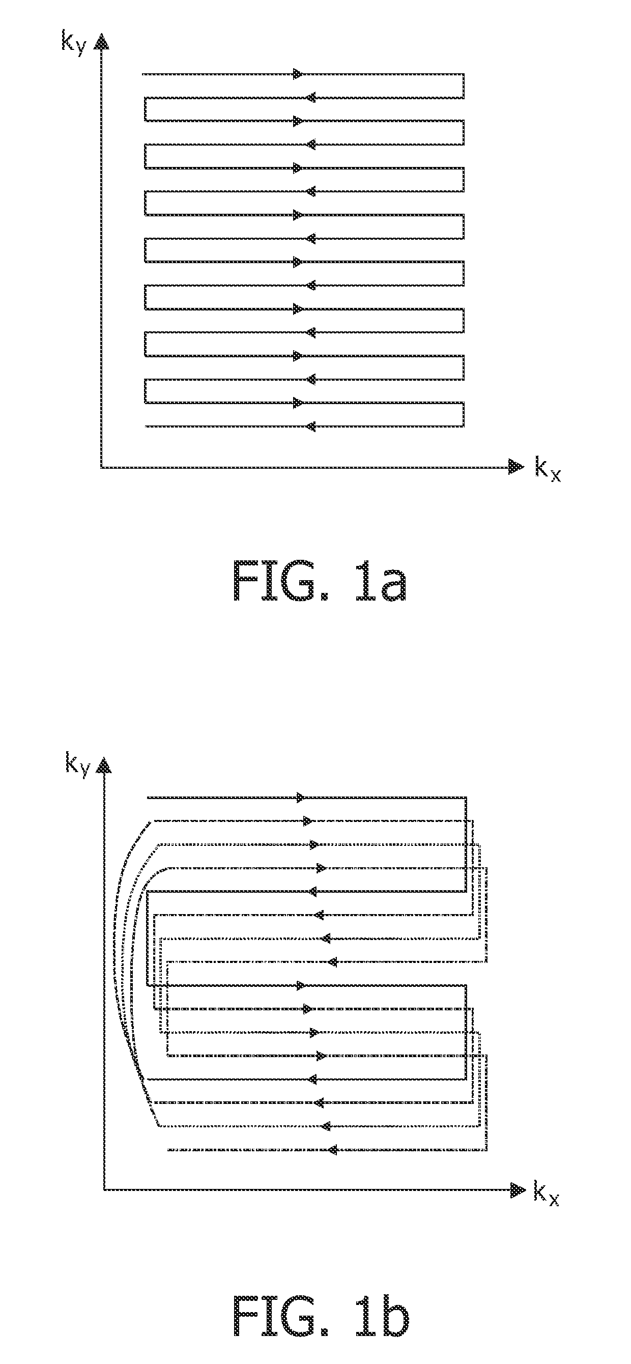
[0032]Conventionally, an EPI sequence traverses k-space as shown in FIG. 1a. The zig-zagging k-space trajectory of the generated and acquired MR echo signals is progressing comparatively slowly in the phase encoding direction ky. The invention proposes a faster progression in k-space by taking larger ky steps, as can be seen in FIG. 1b. In order to fully cover k-space, four separate sub-sequences of MR echo signals are generated in accordance with the shown embodiment. Their k-space trajectories are depicted in FIG. 1b by solid, dashed, dotted, and dashed / dotted lines, respectively. Each sub-sequence traverses a different trajectory in k-space. It is evident that the overall scanning time to acquire and sample MR signals along the complete trajectory shown in FIG. 1b is substantially equal to the time required according to the conventional scheme shown in FIG. 1a. Yet, in the embodiment of FIG. 1b, k-space is traversed four times faster in the phase encoding direction by a single su...


PUM


Abstract

The invention relates to a device for MR imaging of a body (7) placed in an examination volume, the device (1) comprising means (2) for establishing a substantially homogeneous main magnetic field in the examination volume, means (3, 4, 5) for generating switched magnetic field gradients superimposed upon the main magnetic field, means (6) for radiating RF pulses towards the body (7), control means (12) for controlling the generation of the magnetic field gradients and the RF pulses, means (10) for receiving and sampling MR signals, and reconstruction means (14) for forming MR images from the signal samples. According to the invention, the device is arranged to a) generate a sequence of MR echo signals by subjecting at least a portion of the body (7) to a single RF pulse and a plurality of switched magnetic field gradients, the switched magnetic field gradients being controlled to produce at least two subsequences of MR echo signals, wherein each sub-sequence traverses a different trajectory in k-space with subsampling in the phase encoding direction (ky); b) acquire and sample the MR echo signals; c) reconstruct an MR image from the signal samples and from phase / amplitude correction maps associated with the sub-sequences of MR echo signals.

Description

FIELD OF THE INVENTION[0001]The present invention relates to the field of magnetic resonance (MR). It finds particular application in conjunction with MR imaging methods and MR scanners for diagnostic purposes in medicine.BACKGROUND OF THE INVENTION[0002]In MR imaging, pulse sequences consisting of RF pulses and switched magnetic field gradients are applied to an object (a patient) to generate magnetic resonance signals, which are scanned in order to obtain information therefrom and to reconstruct images of the object. Since its initial development, the number of clinical relevant fields of application of MRI has grown enormously. MRI can be applied to almost every part of the body, and it can be used to obtain information about a number of important functions of the human body. The pulse sequence which is applied during an MRI scan determines completely the characteristics of the reconstructed images, such as location and orientation of the image slice in the object, dimensions, re...

Claims


Application Information

Patent Timeline
Patent Type & Authority Applications(United States)
IPC IPC(8): A61B5/05
CPCG01R33/5615G01R33/5616G01R33/56563G01R33/56527G01R33/56554G01R33/565
Inventor FUDERER, MIHA
Owner KONINKLIJKE PHILIPS ELECTRONICS NV
Why Eureka
Try Eureka