Wing-body load alleviation for aircraft

a technology for aircraft and wing bodies, applied in the field of aircraft, can solve the problems of increased drag, limited maneuverability of aircraft, increased wing load, etc., and achieve the effect of reducing wing load and wing load

Active Publication Date: 2009-11-26
THE BOEING CO
View PDF23 Cites 58 Cited by
  • Summary
  • Abstract
  • Description
  • Claims
  • Application Information

AI Technical Summary

Benefits of technology

[0011]A pilot commanded rate of gravity change for commanded normal acceleration and aircraft rate of gravity change response are limited to acceptable magnitudes such that aircraft actuation systems and signal processing is able to deploy wing-body load alleviation control surfaces in accordance with prescribed schedules. In response to initiation of a positive gravity maneuver, airloads are shifted inboard on a swept wing to move the center of pressure forward, thereby reducing the tail load required to perform the positive gravity maneuver and reducing aft body design loads. In response to a negative gravity maneuver, speed brakes are retracted, thereby reducing the positive tail load and reducing the aft body design loads. High gain feedback commands are filtered from wing structural modes above one hertz by a set of linear and non-linear filters.
[0012]Another advantageous embodiment provides a computer program product for symmetric and anti-symmetric control of aircraft flight control surfaces to reduce loads. The computer program product comprises a computer readable medium. The program code stored on the computer readable medium sends commands to symmetrically deploy outboard control surfaces to shift wing air-loads inboard based on airplane state and speed brake deployment of an aircraft. The program code stored on the computer readable medium limits surface rate retraction on a wing with peak loads to reduce maximum loads due to wheel checkback accompanied by utilization of opposite wing control surfaces to retain roll characteristics. The wing-body loads are reduced using the symmetric and anti-symmetric control of the aircraft flight control surfaces.
[0014]The program code stored on the computer readable medium shifts airloads inboard on a swept wing to move a center of pressure forward in response to initiation of a positive gravity maneuver. The tail load required to perform the positive gravity maneuver is reduced. The program code stored on the computer readable medium retracts speed brakes to reduce the positive tail load and aft body design loads during the negative gravity maneuver in response to initiation of a negative gravity maneuver. The program code stored on the computer readable medium filters out high gain feedback commands from wing structural modes above one hertz by a set of linear and non-linear filters.
[0016]Another advantageous embodiment provides an apparatus comprising: a bus system; a communications system connected to the bus system; a memory connected to the bus system, wherein the memory includes computer usable program code; and a processing unit connected to the bus system. The processing unit executes the computer usable program code to send commands to symmetrically deploy outboard control surfaces to shift wing air-loads inboard based on airplane state and speed brake deployment of an aircraft; limit surface rate retraction on a wing with peak loads to reduce maximum loads due to wheel checkback accompanied by utilization of opposite wing control surfaces to retain roll characteristics. The wing-body loads are reduced using the symmetric and anti-symmetric control of the aircraft flight control surfaces.

Problems solved by technology

To compensate for the descent, the lift force is increased by increasing the wing angle, which results in an increase in drag.
This results in an increase in the load on the wings.
Thus, the maneuverability of an aircraft may be limited by the wing size, the available engine power, and the maneuver load on the wings.
Moreover, increases in maneuvering loads on the wings may increase fuel consumption and / or decrease flight speed.
Surface rate retraction on a wing with peak loads is limited to reduce maximum loads due to wheel checkback accompanied by utilization of opposite wing control surfaces to retain roll characteristics.

Method used


Image

  • Wing-body load alleviation for aircraft
  • Wing-body load alleviation for aircraft
  • Wing-body load alleviation for aircraft

Examples


Embodiment Construction

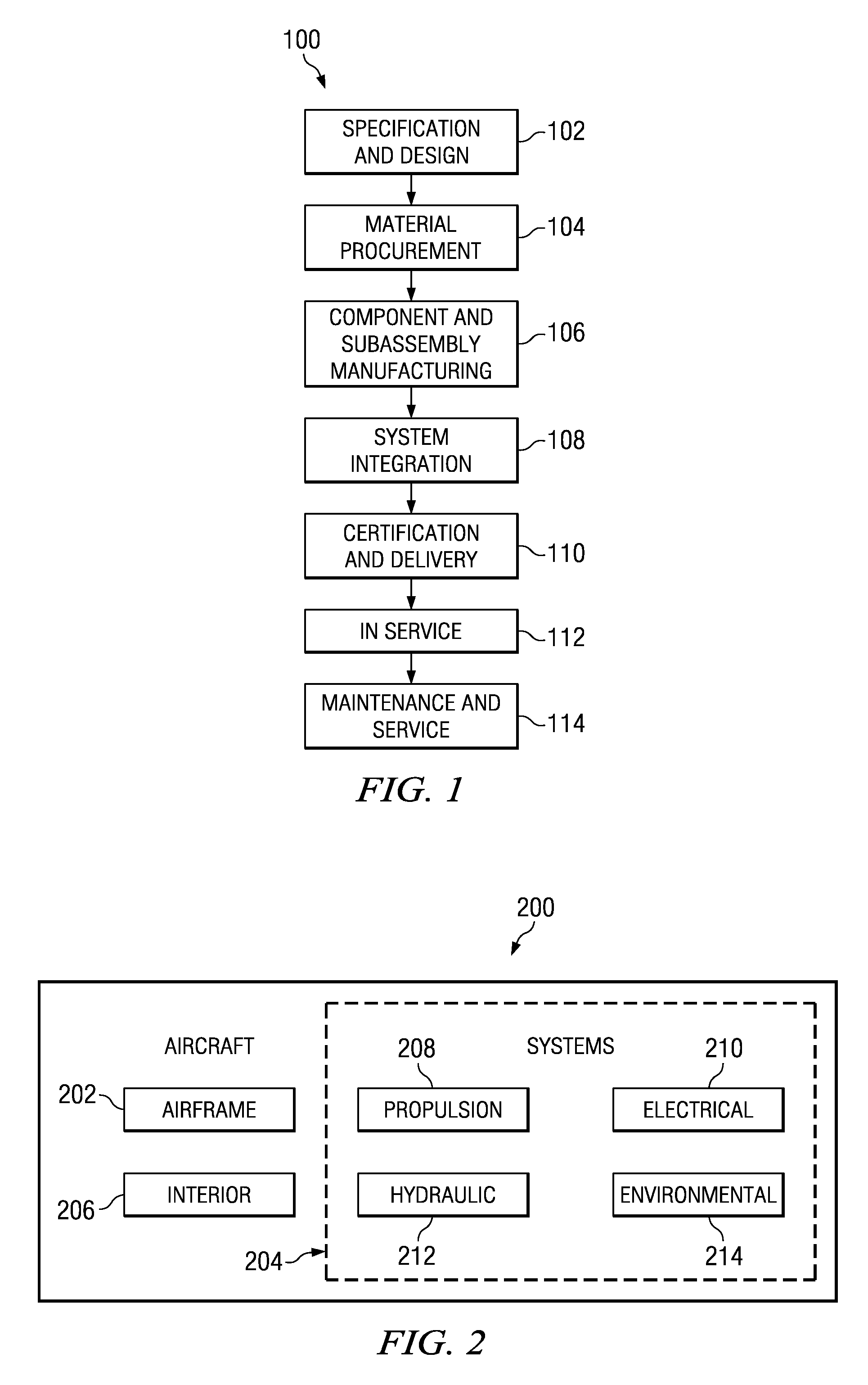
[0035]Referring more particularly to the drawings, embodiments of the disclosure may be described in the context of the aircraft manufacturing and service method 100 as shown in FIG. 1 and aircraft 200 as shown in FIG. 2. Turning first to FIG. 1, a diagram illustrating an aircraft manufacturing and service method is depicted in accordance with an advantageous embodiment. During pre-production, exemplary aircraft manufacturing and service method 100 may include specification and design 102 of aircraft 200 in FIG. 2 and material procurement 104. During production, component and subassembly manufacturing 106 and system integration 108 of aircraft 200 in FIG. 2 takes place. Thereafter, aircraft 200 in FIG. 2 may go through certification and delivery 110 in order to be placed in service 112. While in service by a customer, aircraft 200 in FIG. 2 is scheduled for routine maintenance and service 114, which may include modification, reconfiguration, refurbishment, and other maintenance or s...


PUM


Abstract

A computer implemented method, apparatus, and computer usable program product for symmetric and anti-symmetric control of aircraft flight control surfaces to reduce wing-body loads. Commands are sent to symmetrically deploy outboard control surfaces to shift wing air-loads inboard based on airplane state and speed brake deployment. Surface rate retraction on a wing with peak loads is limited to reduce maximum loads due to wheel checkback accompanied by utilization of opposite wing control surfaces to retain roll characteristics. Airloads are shifted inboard on a swept wing to move the center of pressure forward, thereby reducing the tail load required to perform a positive gravity maneuver. In a negative gravity maneuver, speed brakes are retracted, thereby reducing the positive tail load and reducing the aft body design loads. High gain feedback commands are filtered from wing structural modes above one hertz by a set of linear and non-linear filters.

Description

BACKGROUND INFORMATION[0001]1. Field[0002]The present disclosure relates generally to aircraft and in particular to aircraft control surfaces. More particularly, the present disclosure is directed towards a computer implemented method, apparatus, and computer usable program product for manipulating control surfaces to reduce aircraft wing-body loads.[0003]2. Background[0004]Control surfaces, also referred to as flight controls or actuators, are airfoils that deflect air in one direction and cause an aircraft to move in the opposite direction. As used herein, an aircraft includes, without limitation, an airplane, a helicopter, a carrier, a commercial airliner, a sea plane, or any other type of aircraft.[0005]Control surfaces are manipulated by pilots or by control laws to move an aircraft about its axes of motion and / or change an orientation of the aircraft. Control surfaces are frequently manipulated by using a control yoke, control stick and / or pedals, such as a rudder pedal. Contr...

Claims


Application Information

Patent Timeline
Patent Type & Authority Applications(United States)
IPC IPC(8): B64C13/16B64C3/58
CPCB64C13/16Y02T50/44B64C13/503Y02T50/40
Inventor NAJMABADI, KIOUMARSSHIVITZ, WILLIAM F.COLEMAN, EDWARD ERNESTHO, JOHN KOON-HUNGJOHNSON, RICHARD D.CARVER, WILLIAM F.GRUBB, DAVID W.MCINTOSH, ROBERT JAMES
Owner THE BOEING CO
Why Eureka
Try Eureka