Transformer-capacitor enhancement circuitry for power amplifiers

Active Publication Date: 2009-12-03
QUALCOMM INC
View PDF5 Cites 9 Cited by
  • Summary
  • Abstract
  • Description
  • Claims
  • Application Information

AI Technical Summary

Benefits of technology

[0009]The present invention is directed to an improved method for allowing improved pulse-type enhancement of the voltage supplied to a power amplifier fed by a power supply being connected to the power amplifier at a first feeding point through a main supply path connected via a first inductor having a high impedance to an enhancement pulse at the feeding point, and to a second feeding point. A first supplementary supply path is used for providing enhanced operating voltage to the power amplifier that is connected to a first power supply. A pair of a first and a second controllable impedances that are connected by a common contact is provided and have a separate control input and being capable of being in a non-conduct

Problems solved by technology

However, the level of enhancement provided by the circuitry of has not been sufficient for more high power applications.
In addition, in the circuit of U.S. Pat. N

Method used


Image

  • Transformer-capacitor enhancement circuitry for power amplifiers
  • Transformer-capacitor enhancement circuitry for power amplifiers
  • Transformer-capacitor enhancement circuitry for power amplifiers

Examples


Embodiment Construction

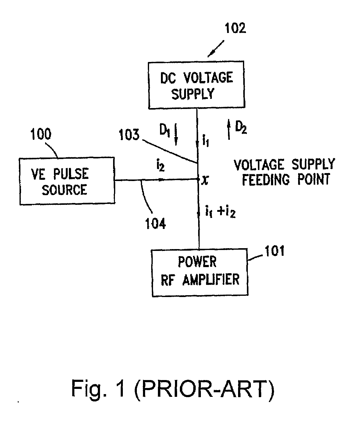
[0026]FIG. 1 is a block diagram of a circuitry that controls the level of enhancement of the voltage supplied to a power amplifier, according to prior art. The power amplifier 101 is supplied with operating voltage through a feeding point x, which is connected to a DC voltage supply 102 via the main supply path 103, and to a voltage enhancement pulse source 100, via a supplementary supply path 104. The Voltage Enhancement (VE) circuitry 100 increases the supply voltage at the feeding point x for a relatively short duration (in the order of the reciprocal of the modulation bandwidth), when voltage enhancement is required. Under normal operation conditions (i.e., when no enhancement is required), the feeding point x has an extremely low resistance to the DC current i1 consumed from the DC voltage supply circuitry 102 (in the direction D1). During the same normal operation period, the VE pulse source 100 causes feeding point x to have an extremely low impedance to all the frequency com...


PUM


Abstract

Circuitry for providing improved pulse-type enhancement of the voltage supplied to a power amplifier (101) that is fed by a power supply that is connected to the power amplifier (101) at a feeding point through a main supply path that is connected via an inductor (L1). A second feeding point is used for enhancement by a capacitor that is discharged. A transformer L2, L3, M) is formed by mutually coupling an additional inductor (L3), through which an additional supply path is connected. Enhancement power is provided partially through the transformer L2, L3, M) and the remaining part thorough the capacitor (C1). This way, the total level of possible enhancement is increased, while minimizing distortion of the envelope of the amplified RF signal.

Description

FIELD OF THE INVENTION[0001]The present invention relates to the field of high efficiency power amplifiers. More particularly, the invention relates to a circuitry for efficiently controlling the impedance at a connection point of a power supply to a power amplifier, being a feeding point, and providing enhancement of the voltage that is delivered to said power amplifier via supplementary supply paths that are used to connect the power supply to that point.BACKGROUND OF THE INVENTION[0002]Several RF systems containing power amplifiers are characterized in recurrent periods of signals having large peak excursions, which should be handled, in order to improve the efficiency of these systems. One way to handle signals with large peak-to-average ratios is to control the DC power supply to a power amplifier. One voltage level is supplied to such a power amplifier whenever the instantaneous amplitude is below a given level (normal operating condition), and an enhanced (and higher) voltage...

Claims


Application Information

Patent Timeline
IPC IPC(8): H03F1/00
CPCH03F1/0211H03F1/32H03F2200/271H03F2200/511H03F2200/351H03F2200/504H03F2200/273H03F1/0244
Inventor BAR-DAVID, ISRAELVEINBLAT, ALEXANDER
Owner QUALCOMM INC
Why Eureka
Try Eureka