Coil Component and Its Manufacturing Method

a manufacturing method and coil technology, applied in the field of coil components, can solve the problems of insufficient impedance at a high frequency, and the inability to handle high-speed transmission applications with the conventional coil components, and achieve the effect of maintaining initial magnetic permeability and easy magnetization plan

Inactive Publication Date: 2009-12-03
HITACHI METALS LTD
View PDF10 Cites 29 Cited by
  • Summary
  • Abstract
  • Description
  • Claims
  • Application Information

AI Technical Summary

Benefits of technology

[0009]A coil component of the present invention is characterized in that a coil member having a plurality of coil lines laminated through an insulating layer is sandwiched by hexagonal ferrite substrates and the hexagonal ferrite substrates have anisotropy. Here, having the “anisotropy” means that alignment of crystal orientation is different according to a direction of a substrate, in other words, that the hexagonal ferrite substrate has anisotropy in a c-axis orientation of a ferrite crystal grain. The hexagonal ferrite is a magnetic material that can maintain initial magnetic permeability up to a high frequency since it has magnetic anisotropy having a direction orthogonal to the c-axis as an easy magnetization plane. As the result of this “anisotropy”, the initial magnetic permeability is different according to direction.

Problems solved by technology

In the conventional coil component as mentioned above, Ni—Zn spinel (cubic) ferrite is mainly used as the magnetic substrate, but since the spinel ferrite has its initial magnetic permeability lowered at a relatively low frequency, an impedance at a high frequency is not necessarily sufficient.
Particularly for high-speed transmission application of 800 Mbps or more as in IEEE1394b, since it is difficult to ensure sufficient impedance, the high-speed transmission application can not be handled with the conventional coil component.

Method used


Image

  • Coil Component and Its Manufacturing Method
  • Coil Component and Its Manufacturing Method
  • Coil Component and Its Manufacturing Method

Examples


first embodiment

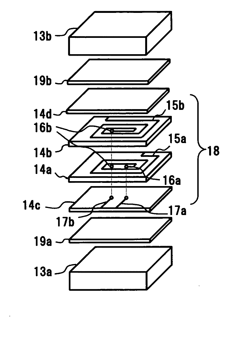
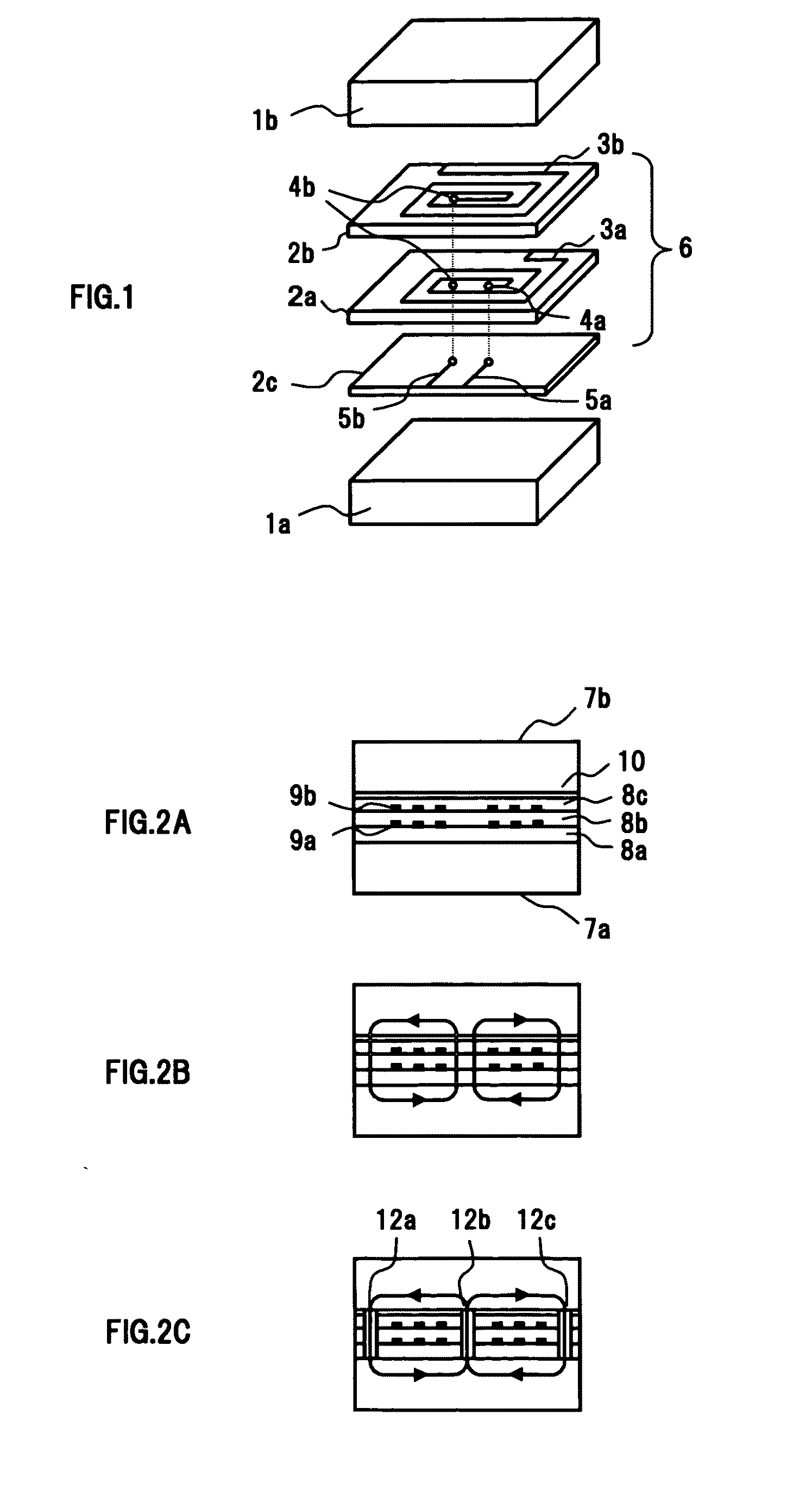
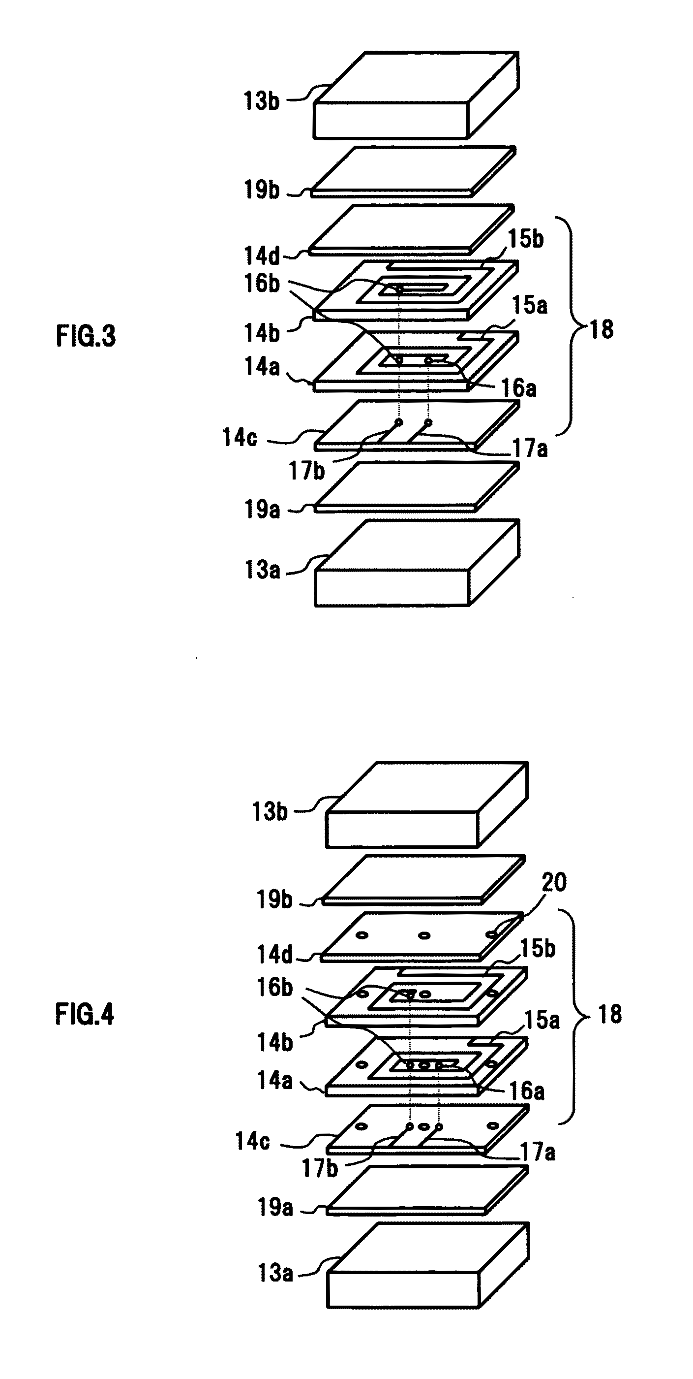
[0048]FIG. 3 is an exploded perspective view illustrating a first embodiment of a coil component of the present invention. The coil component of the present embodiment is a common mode choke coil, but the coil component of the present invention is not limited to the common mode choke coil, but choke coils and transducers for other applications may be used, and size reduction and improvement in frequency characteristics of these coil components can be realized.

[0049]In the coil component shown in FIG. 3, a coil member 18 having a plurality of coil lines (15a, 15b) laminated through a nonmagnetic insulating layer 14b is sandwiched by hexagonal ferrite substrates (13a, 13b) constituted by a sintered body. As shown in FIG. 3, the hexagonal ferrite substrates (13a, 13b) having a flat-plate, rectangular solid shape sandwich the coil member 18 in a direction of a winding axis of a coil. With the configuration shown in FIG. 3, the coil member is further provided with an insulating layer 14c...

second embodiment

[0062]FIGS. 4 and 5 are views for explaining a second embodiment of the coil component of the present invention, in which FIG. 4 is an exploded perspective view of the coil component of this embodiment and FIG. 5 is an outline diagram of the coil component. In FIG. 5, the through holes (16a, 16b) are not shown. Also, in FIGS. 4 and 5, the same reference numerals are given to the same members as those in the first embodiment. The coil component of this embodiment has a magnetic layer 20b inside the coil line and magnetic layers 20a and 20c on the outside in addition to the configuration of the above first embodiment. Specifically, the magnetic layers 20a, 20b, and 20c penetrate the coil member 18 in the laminate direction. Such configuration will be described below using the exploded perspective view in FIG. 4. The configuration other than the magnetic layer 20 is the same as that of the first embodiment, and the explanation will be omitted.

[0063]The magnetic layer 20 penetrating the...

third embodiment

[0068]FIGS. 6 and 7 are diagrams for explaining a third embodiment of the coil component of the present invention, in which FIG. 6 is an exploded perspective view of the coil component of the third embodiment and FIG. 7 is an outline diagram of a section of the coil component. These figures show another example in which a magnetic layer is provided at least at a portion of the inner side and the outer side of the coil line. In FIG. 7, the through holes (16a, 16b) are not shown. Also, in FIGS. 6 and 7, the same reference numerals are given to the same members as those in the first and second embodiments.

[0069]In this embodiment, in addition to the configuration of the above first embodiment, a magnetic layer 21b on the inner side and magnetic layers 21a and 21c on the outer side of the coil line are provided. Specifically, the magnetic layers 21a, 21b, and 21c are formed by being laminated alternately with the insulating layer in the laminate direction of the coil member 18, that is,...


PUM

PropertyMeasurementUnit
frequencyaaaaaaaaaa
densityaaaaaaaaaa
relative permittivityaaaaaaaaaa

Abstract

In a coil component of the present invention, a coil member having a plurality of coil lines laminated through an insulating layer is sandwiched by hexagonal ferrite substrates, and the hexagonal ferrite substrate has anisotropy. To have the “anisotropy” means that alignment of the crystal orientation is different according to a direction of the substrate, in other words, that anisotropy is provided in the c-axis orientation of ferrite crystal grains of the hexagonal ferrite substrate. As the result of the “anisotropy”, an initial magnetic permeability is also different according to direction. By using the hexagonal ferrite substrate as a magnetic substrate to sandwich the coil member so as to form a magnetic path, the initial magnetic permeability can be maintained up to a high frequency, and a high-frequency characteristic of impedance generated by the coil lines can be improved.

Description

TECHNICAL FIELD[0001]The present invention relates to a coil component excellent in impedance characteristic at a high frequency or particularly to a coil component used as a transducer, common mode filter and the like.BACKGROUND ART[0002]Higher signal transmission speed and higher driving frequency have progressed in electronic equipment such as a personal computer, cellular phone and the like. For example, standards such as IEEE1394a with transmission rate of 400 Mbps and USB2.0 with transmission rate of 480 Mbps have been prevailing and higher speed HDMI (700 Mbps) and IEEE1394b (800 Mbps) are expected to come. Coil components such as common mode filter used in these types of high-speed differential transmission need to correspond to a high frequency, small in size and the like.[0003]FIG. 1 is an exploded perspective view illustrating a configuration example of a conventional small-sized coil component used as a transducer, common mode filter and the like. As shown in this figure...

Claims


Application Information

Patent Timeline
Patent Type & Authority Applications(United States)
IPC IPC(8): H01F27/30H01F7/06
CPCC01G49/009Y10T29/4902C04B35/2633C04B35/6262C04B35/62685C04B2235/3203C04B2235/3215C04B2235/3263C04B2235/3277C04B2235/3418C04B2235/5409C04B2235/605C04B2235/767C04B2235/77C04B2235/787H01F1/348H01F27/2804H01F41/043H01F2017/002H01F2027/2809H01F2027/2819C01G53/006
Inventor MIKAMI, HIDETOKATO, TOMOTSUGUNAKADA, MIYAKONOGUCHI, SHIN
Owner HITACHI METALS LTD
Why Eureka
Try Eureka