
Process for preparing high frequency high power ferrite material

A ferrite material, high-power technology, applied in the field of materials, can solve the problem of the material design system is not very perfect, not to mention design and so on

Inactive Publication Date: 2007-07-25
UNIV OF ELECTRONICS SCI & TECH OF CHINA
View PDF0 Cites 21 Cited by
  • Summary
  • Abstract
  • Description
  • Claims
  • Application Information

AI Technical Summary

Problems solved by technology

[0003] At present, well-known research institutions and universities at home and abroad still use the so-called "cooking" method of research on materials, which also includes the flag of the world's ferrite industry - TDK Corporation of Japan. The research and development of materials is mainly based on a large number of repetitive experiments, and the material design system is not very perfect; as far as the country is concerned, because the main focus of production is low- and medium-grade ferrite materials, the material design system is not perfect. Basically it can be said to be blank, basically it can be said to be a typical "fried dish" style, not to mention the design

Method used


Image

  • Process for preparing high frequency high power ferrite material
  • Process for preparing high frequency high power ferrite material
  • Process for preparing high frequency high power ferrite material

Examples


preparation example Construction

[0029] The preparation method of 1~3MHz high-frequency high-power ferrite material of the present invention comprises the following steps:

[0030] The raw material adopts 51~55mol% Fe 2 o 3 , 5 ~ 10mol% ZnO, the balance is MnCO 3 ;

[0031] 1) Ball milling and mixing: mill the above powder in a ball mill for 1 to 6 hours to make the powder evenly mixed;

[0032] 2) Pre-burning: Pre-burning the ball abrasive obtained in step 1 in a furnace at 800-1000°C for 1-5 hours;

[0033] 3) Doping: Add the following additives to the powder obtained in step 2 by weight: 0.01-0.4wt% CaO, 0.00-0.5wt% TiO 2 , 0.00~0.3wt%SnO 2 , 0.01~0.2wt% Nb 2 o 5 And 0.01~0.1wt% K 2 CO 3 ;

[0034] 4) secondary ball milling: milling the powder obtained in step 3 in a planetary ball mill for 10 to 20 hours;

[0035] 5) Molding: add 8-12wt% organic binder to the powder obtained in step 4 according to the weight ratio, mix well, and after granulation, press the granular powder on a press to form a ...

example 1~15

[0039] 1) Using 53mol% Fe 2 o 3 , 8.5mol% ZnO, the balance is MnCO 3 ; Mill the above powder in a ball mill for 4 hours to make the powder evenly mixed;

[0040] 2) Pre-burning: Pre-burning the ball abrasive obtained in step 1) in a furnace at 950°C for 1.5 hours;

[0041] 3) Doping: Add the following additives to the powder obtained in step 2) by weight: 0.3wt% CaO, 0.025wt% Nb 2 o 5 , 0.05wt% K 2 CO 3 and different amounts of TiO 2 and SnO 2 , where TiO 2 and SnO 2 The corresponding addition amount is shown in Table 1 (corresponding to Examples 1-15); the material powder is ball-milled in a planetary ball mill for 16 hours;

[0042] Table 1

[0043]

example

CaO(wt%)

Nb 2 o 5 (wt%)

K 2 CO 3 (wt%)

TiO 2 (wt%)

SnO 2 (wt%)

1

0.3

0.025

0.05

0

0

2

0.3

0.025

0.05

0

0.05

3

0.3

0.025

0.05

0

...


PUM


Abstract

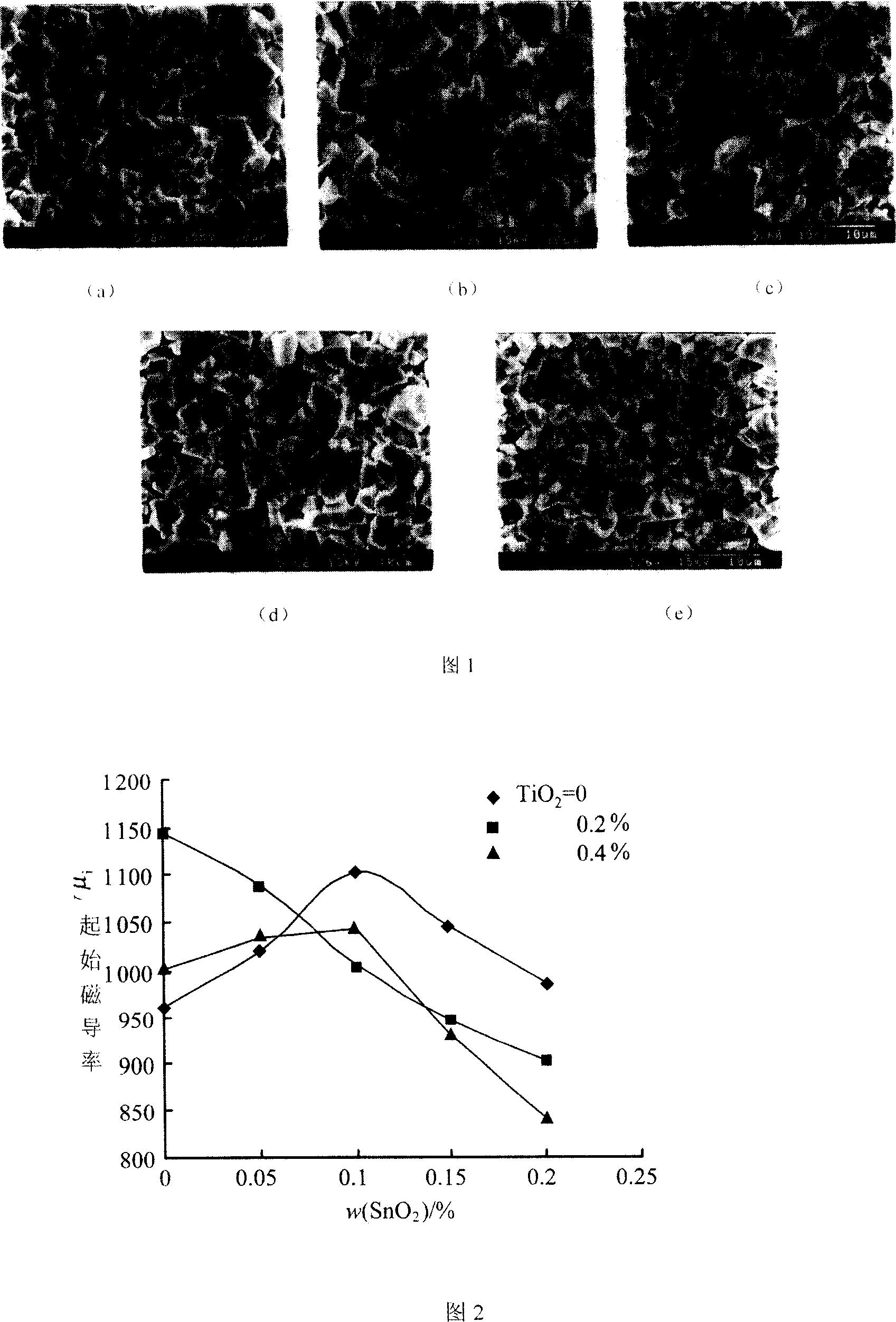
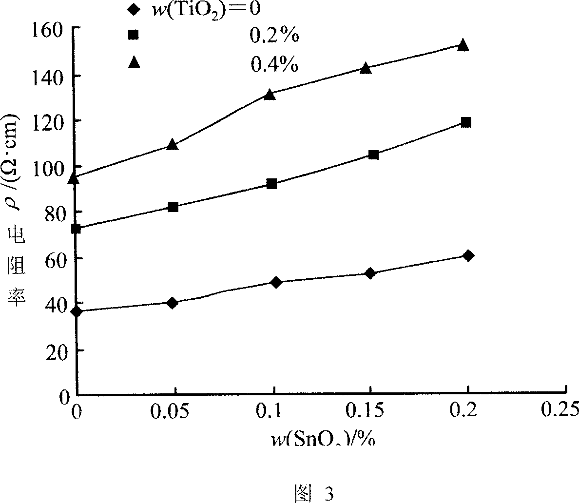
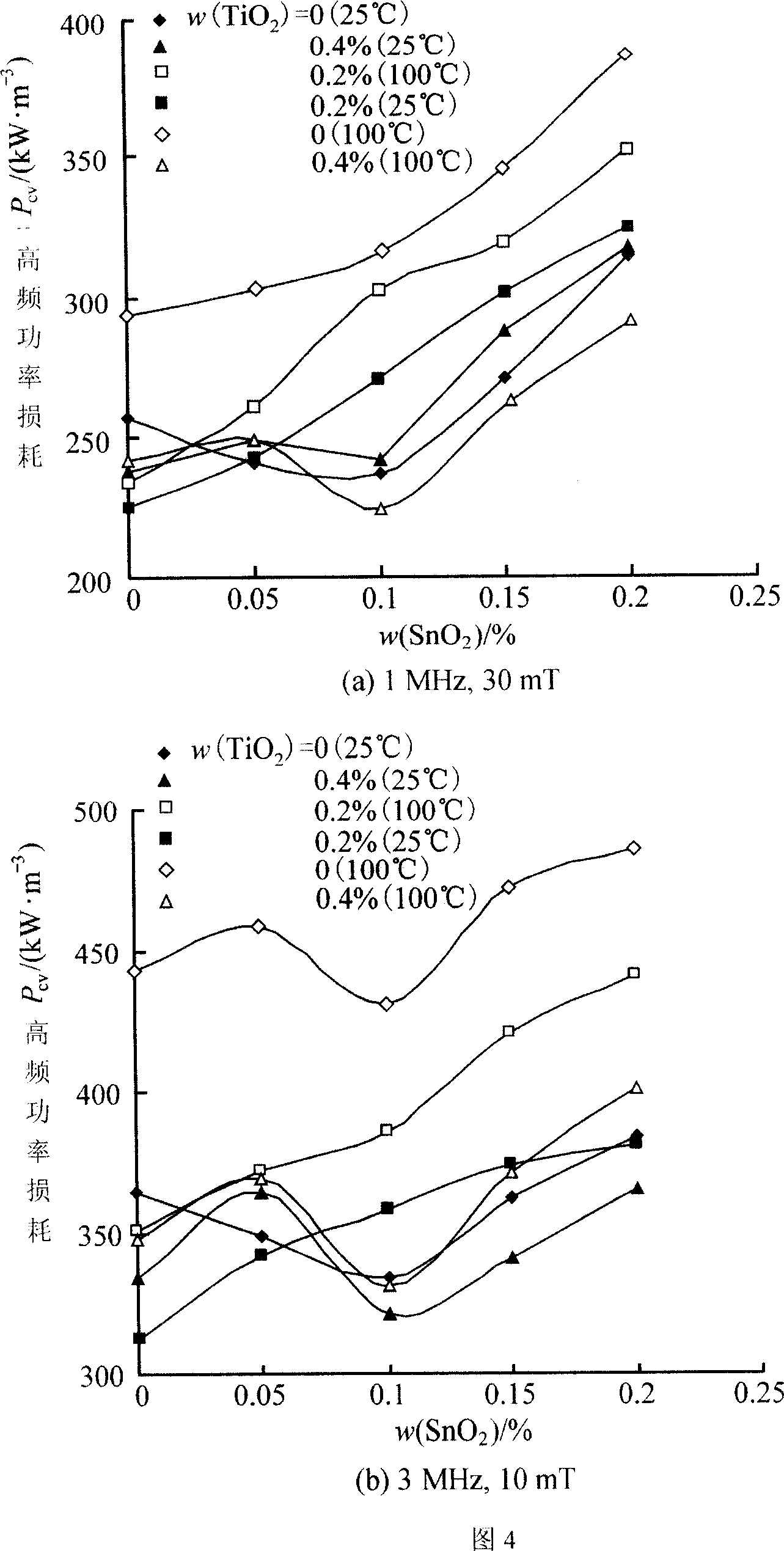
The method includes following steps: (1) mixing step, mixing powder materials 51-55 mol% Fe2O3, 5-10mol% ZnO, and residual MnCO3 uniformly; (2) preburning step, preburning mixture obtained from step (1); (3) doping step, adding additives according to following mass ratios to the mixture: 0.01-0.4wt% CaO, 0.01-0.2wt% Nb2O5, 0.01-0.1wt% K2CO3, and not exceeding 0.5wt% TiO2, and not exceeding 0.3wt% SnO2; (4) second ball milling step, ball milling powder material obtained from step (3) again; (5) molding step, adding 8-12wt% organic binding agent to powder material obtained from step (4), and after mixing and granulating, pressing powder material to blank; (6) aura sintering, placing blanks into sintering furnace to be sintered. Advantages of the MnZn power ferrite material are: fine microstructure, high initial permeability, and lower power loss under high frequency.

Description

technical field [0001] The invention belongs to material technology, in particular to design and preparation technology of high-frequency power ferrite material. Background technique [0002] With the continuous development of power electronics technology, power electronics has become one of the research hotspots in the field of electronic information. Therefore, magnetic devices used for power transmission and conversion must have good high-frequency characteristics, which requires power ferrite materials to have high application frequency, wide temperature and low loss characteristics, so we use power ferrite materials The research on the design and preparation technology will play a decisive role in the development of the information industry and power electronics. [0003] At present, well-known research institutions and universities at home and abroad still use the so-called "cooking" method of research on materials, which also includes the flag of the world's ferrite ...

Claims


Application Information

Patent Timeline
IPC IPC(8): H01F1/10C04B35/26C04B35/622
Inventor 孙科余忠兰中文
Owner UNIV OF ELECTRONICS SCI & TECH OF CHINA
Learn More