Fiber laser coil form and related manufacturing techniques

Inactive Publication Date: 2009-12-03
MORGAN RES CORP
View PDF0 Cites 35 Cited by
  • Summary
  • Abstract
  • Description
  • Claims
  • Application Information

AI Technical Summary

Benefits of technology

[0059]The fiber coiler may further include a thermal grease applicator to apply a thermal grease to the fiber to enhance a thermal contact between the fiber and the coil form.
[0060]The coil form may include a thermally conductive substrate to support the fiber and to dissi

Problems solved by technology

Because laser fibers may radiate heat during a lasing process, the amount of heat produced may affect heat-sensitive components of the fiber laser or may reduce an efficiency of the fiber laser.
For example, because the fiber is manually wound around the mandrel, there is an increased chance that the fiber will cross over itself as it is wound.
This leads to hot-spots at cross-over locations.
These hot-spots may affect the dimensions of the laser and thus, affect a shift in the frequency of t

Method used


Image

  • Fiber laser coil form and related manufacturing techniques
  • Fiber laser coil form and related manufacturing techniques
  • Fiber laser coil form and related manufacturing techniques

Examples


Embodiment Construction

[0094]Reference will now be made in detail to embodiments of the present invention, examples of which are illustrated in the accompanying drawings, wherein like reference numerals refer to the like elements throughout. The embodiments are described below in order to explain the present invention by referring to the figures.

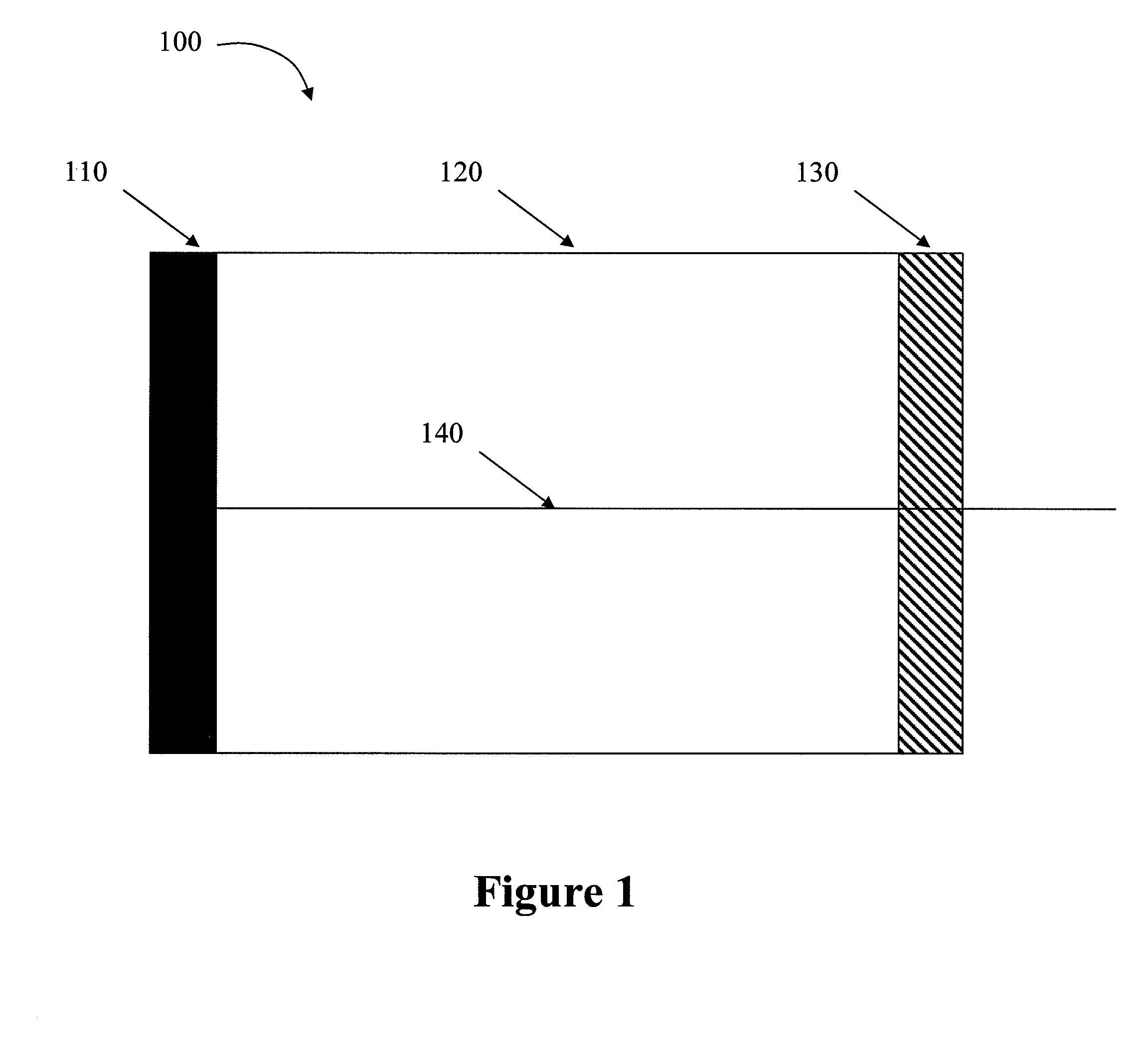
[0095]FIG. 1 illustrates a conventional laser. As illustrated in FIG. 1, a laser 100 may include a reflector 110, an active gain medium 120, and an output coupler 130. Laser 100 can be operated by inputting energy, i.e. “pumping”, into the active gain medium 120 via an external energy source, including, but not limited to, electrical current, flashlamp, light from another laser, radio-frequency (RF), or the like.

[0096]The active gain medium 120 can be made of various materials, each of which will emit radiation of a different frequency. Selection of the appropriate active gain medium depends upon the desired characteristics of the output radiation, such as frequen...


PUM

PropertyMeasurementUnit
Electrical conductoraaaaaaaaaa
Adhesivityaaaaaaaaaa
Contentaaaaaaaaaa

Abstract

A fiber laser thermal coil form and related manufacturing techniques that are substantially suitable for automation. The fiber laser thermal coil form including a thermally conductive substrate to support a fiber placed thereon and to dissipate a heat of the fiber, and a fiber guide groove defined in a surface of the substrate to guide the fiber and dimensioned to partially enclose the fiber and to enhance a thermal contact of the fiber and the substrate.

Description

CROSS-REFERENCE TO RELATED APPLICATIONS[0001]This application claims priority from U.S. Provisional Patent Application Ser. No. 61 / 036,950, filed on Mar. 15, 2008, the disclosure of which is hereby incorporated by reference in its entirety.COPYRIGHT NOTIFICATION[0002]This application includes material which is subject to copyright protection. The copyright owner has no objection to the facsimile reproduction by anyone of the patent disclosure, as it appears in the Patent and Trademark Office files or records, but otherwise reserves all copyright rights whatsoever.BACKGROUND OF THE INVENTION[0003]1. Field of the Invention[0004]The present application relates to fiber lasers and fiber laser coils, and more particularly, to fiber laser coil forms, and methods and apparatuses to fabricate fiber lasers using the same.[0005]2. Description of the Related Art[0006]The ability of lasers to efficiently deliver coherent monochromatic light has made them popular in household, commercial, medica...

Claims


Application Information

Patent Timeline
IPC IPC(8): H01S3/30B65H75/04B65H75/18B65H54/00B21F3/04B65H81/00
CPCG02B6/3636H01S3/06704H01S3/09415H01S3/094007H01S3/0675
Inventor HEATON, LARRY CHRISTOPHERWILLIAMS, JEFF
Owner MORGAN RES CORP
Why Eureka
Try Eureka