Scanning temporal ultrafast delay and methods and apparatuses therefor

a technology of ultrafast delay and scanning time, which is applied in the field of ultrashort pulsewidth lasers, can solve the problems of large space required if large delays are desired, physical delay methods suffer, and other physical limitations, and achieve the effect of rapid scanning and improving the duty cycle of data acquisition

Inactive Publication Date: 2009-12-03
IMRA AMERICA
View PDF8 Cites 23 Cited by
  • Summary
  • Abstract
  • Description
  • Claims
  • Application Information

AI Technical Summary

Benefits of technology

[0027]It is an object of the present invention to provide a method and apparatus for rapidly scanning the time delay between two modelocked lasers, e.g., “master” and “slave” lasers, without the need for large mechanical movements of optical elements, which would allow scanning of any selected, contiguous subinterval of the pulse repetition period TR. This is accomplished by making appropriate adjustments, on the order of microns, to the cavity length of one laser (e.g., the slave laser), while using an electronic feedback circuit to continually monitor the average timing (phase) between the two lasers. Additionally, it is desired to modify the RF stabilization of the two lasers in such a way that, unlike the free-scanning laser method, the relative time delay can be scanned over some sub-interval of the repetition period, thus greatly improving the duty cycle of data acquisition.
[0028]It is another object of the present invention to minimize the timing jitter caused by fluctuations in environmental conditions, such as vibration, air turbulence, and varying temperature. This is accomplished by constructing both lasers with identical elements within the same enclosure, and pumping them with the same pump laser, yet allowing them to be independently controlled. In particular, in the case of fiber lasers, it can be accomplished by co-wrapping the fibers together on the same spool.

Problems solved by technology

The physical delay methods suffer from a number of disadvantages, the chief one being the large space required if large delays are desired.
There are other physical limitations and disadvantages as well.
Misalignment and defocusing can distort measurements when large delays are used.
This is impractically large for many situations.
The need for large mirror displacement can be reduced by multi-passing the delay line (e.g., double-passing the delay line cuts the required mirror displacement in half), however, this does not alleviate the defocusing problem.
Multipassing causes its own set of problems in that alignment procedures are more complicated, and the optical losses are increased.
Yet another limitation has to do with the scanning rates and scanning frequencies which can be achieved simultaneously.
However, the scanning range is limited at such high scan frequencies.
Any further increase of the scanning range and / or frequency with such reciprocating devices would cause high levels of vibration, which can be disruptive to laser operation.
Rotating glass blocks avert the vibration problem, and are capable of higher scan speed, but lack any adjustability of scan range, and they introduce variable group velocity dispersion which makes them inappropriate for use with pulses having widths shorter than 100 fsec.
The chief drawback to this technique is that it is highly wasteful of data acquisition time for two main reasons:1. Fixed scan range—The scan range is fixed at the inverse of the repetition frequency (i.e., the round trip time) of the laser.2. Dead time—One is often interested in only a 100 psec, or 10 psec scan range instead of the full 13 nsec pulse spacing.
However, this solution is unacceptable for many applications which require a large variety of scan ranges.
Lifetimes of carriers (i.e., electrons and holes) of the semiconductor are on the order of several nanoseconds which makes a 1 GHz laser completely unacceptable, since residual carriers from the previous laser pulse would still be present when the next pulse arrives.
Thus, the free-scanning laser technique lacks the versatility of scan range selection which is required in many applications.
However, this method suffers from the same lack of timing adjustability as the passive optical methods.
However, it should be noted the object of Dykarr et al. is to lock the two lasers together, which is undesirable for the purposes of the present invention, because then the time delay cannot be scanned; i.e., the timing of the pulses from the two coupled lasers of the Sticky-Pulse laser discussed above, are locked together through the optical coupling and they cannot be independently controlled.

Method used


Image

  • Scanning temporal ultrafast delay and methods and apparatuses therefor
  • Scanning temporal ultrafast delay and methods and apparatuses therefor
  • Scanning temporal ultrafast delay and methods and apparatuses therefor

Examples


Embodiment Construction

[0045]The embodiments of the present invention are described below in more detail with reference to the above drawings, in which like reference numerals refer to the same or similar elements.

Principle of Fast Scanning Method

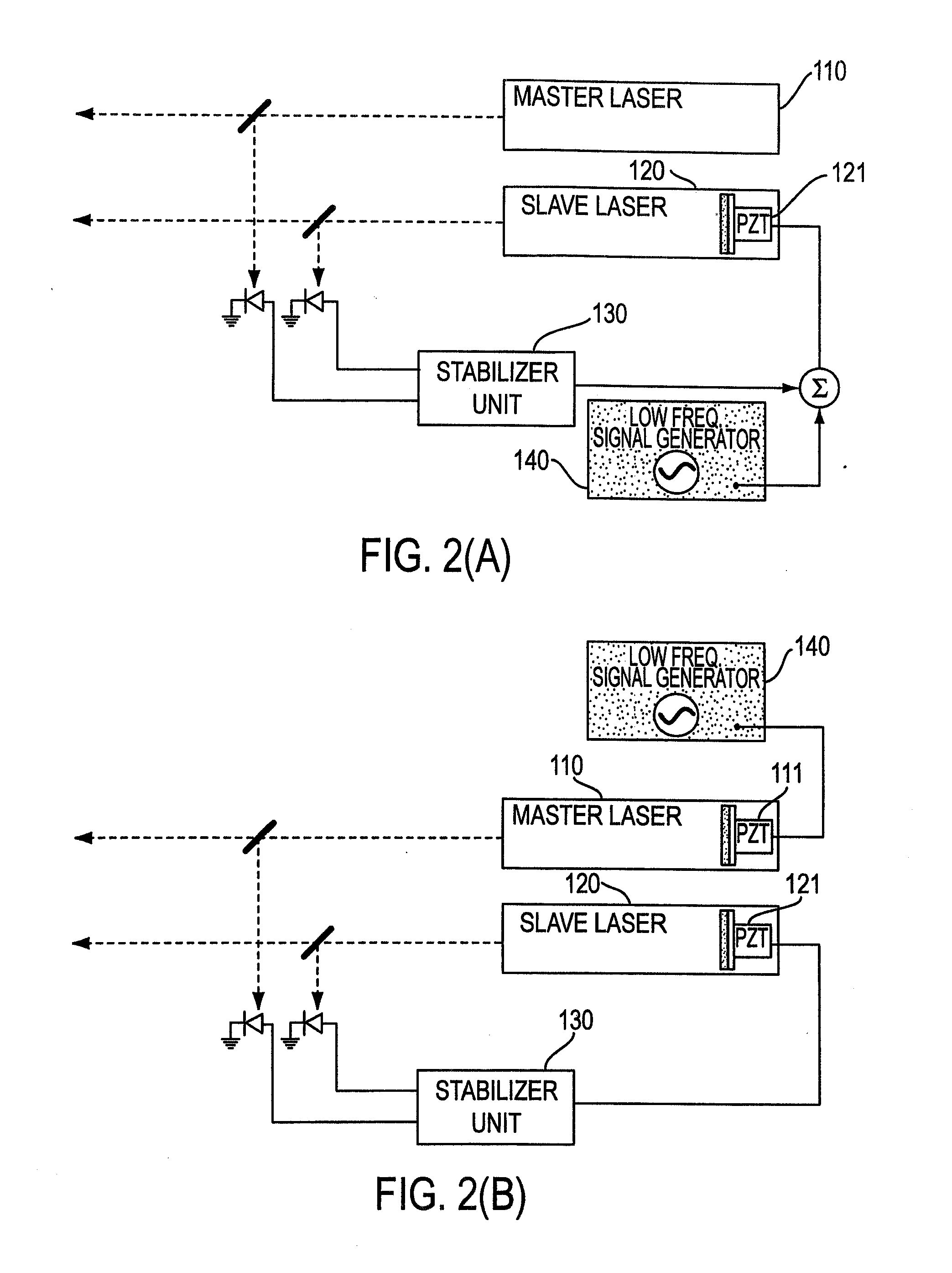
[0046]The present invention, like the free-scanning laser system, consists of two lasers, a master laser 110 and a slave laser 120, which have nearly identical repetition rates as shown, for example, in FIG. 2(A). However, unlike the free-scanning laser system, pulses output from the master and slave lasers are not allowed to totally scan through each other. Rather, while master laser 110, which has a wavelength λ1, is held at a constant repetition rate v1 or is allowed to drift of its own accord, the repetition frequency v2 of slave laser 120 is dithered about the repetition rate of master laser 110. This dithering of the repetition rate is accomplished by changing the cavity length (L2) of slave laser 120 at a “high” frequency, for example, in the range of 30 H...


PUM


Abstract

The present invention is directed to methods and apparatuses for performing temporal scanning using ultra-short pulsewidth lasers in which only minimal (micro-scale) mechanical movement is required. The invention also relates to methods for obtaining high-accuracy timing calibration, on the order of femtoseconds. A dual laser system is disclosed in which the cavity of one or more of the lasers is dithered, by using a piezoelectric element. A Fabry-Perot etalon is used to generate a sequence of timing pulses used in conjunction with a laser beam produced by the laser having the dithered laser cavity. A correlator correlates a laser pulse from one of the lasers with the sequence of timing pulses to produce a calibrated time scale. The methods and apparatuses of the present invention are applicable to many applications requiring rapid scanning and time calibration, including, but not limited to metrology, characterization of charge dynamics in semiconductors, electro-optic testing of ultrafast electronic and optoelectronic devices, optical time domain reflectometry, and electro-optic sampling oscilloscopes.

Description

BACKGROUND OF THE INVENTION[0001]1. Field of the Invention[0002]This invention is related to the field of ultra-short pulsewidth lasers, and particularly to apparatuses and methods for performing temporal scanning with minimal (i.e., micron-scale) mechanical movement. The invention also relates to methods used for obtaining high-accuracy (i.e., sub-picosecond) timing calibration, applicable to the above-mentioned temporal scanning methods or to conventional temporal scanning methods. In particular, the invention eliminates the need for a mechanical scanning delay arm in a correlator or other type of pump-probe device, including ranging, 3-D imaging, contouring, tomography, and optical time-domain reflectometry (OTDR).[0003]2. Description of the Related Art[0004]Ultrafast laser oscillators are presently known which are capable of generating pulsewidths of the order of tens of femtoseconds with nanojoule-level pulse energies, at repetition rates ranging from 5 MHz to as high as 1 GHz....

Claims


Application Information

Patent Timeline
Patent Type & Authority Applications(United States)
IPC IPC(8): H01S3/30H01S3/13H01S3/10G01B11/24G01M11/00G01P3/80G01R13/34G01S7/48G01S7/484G01S7/486G01S17/18G01S17/50H01S3/02H01S3/06H01S3/07H01S3/098H01S3/105H01S3/139H01S3/23
CPCG01P3/806G01R13/347G01S7/484G01S7/486G01S7/497G01S17/50H01S3/1398H01S3/2383G01S17/107G01S17/18
Inventor SUCHA, GREGG D.FERMANN, MARTIN E.HARTER, DONALD J.
Owner IMRA AMERICA
Why Eureka
Try Eureka