Integrated Vacuum Gripper with Internal Releasable Magnet and Method of Using Same

a vacuum gripper and magnet technology, applied in the field of vacuum grippers with internal releasable magnets and methods of using them, can solve the problems of requiring additional structure, requiring redundant gripping mechanisms and/or friction, and too high precision to be lifted without mechanical assistance, so as to increase flexibility and reduce investment costs

Inactive Publication Date: 2009-12-03
GM GLOBAL TECH OPERATIONS LLC
View PDF14 Cites 24 Cited by
  • Summary
  • Abstract
  • Description
  • Claims
  • Application Information

AI Technical Summary

Benefits of technology

[0005]A unique integrated lifting and transport device providing increased flexibility and lower investment costs is provided. The lifting and transport device includes a rigid housing defining an internal chamber. A flexible vacuum cup having an interface end is operatively connected to the rigid housing. The flexible vacuum cup also has a sealing and gripping end opposite the interface end, and a vacuum cavity defined between the gripping end and interface end.

Problems solved by technology

Industrial manufacturing processes often include repetitive lifting and transportation of work pieces that are too heavy, too large, too fragile, or must be placed with too high precision to be lifted without mechanical assistance.
Furthermore, vacuum grippers are capable of generating gripping force in only a single direction (created by air pressure on the opposite side of the vacuum chamber) and may require redundant gripping mechanisms and / or friction to hold the work piece while rotating or moving along more than one axis.
However, these grippers often require additional structure to mechanically release the work piece from the gripper and work only on ferrous materials.
Additionally, permanent magnet grippers are often incapable of picking up only one work piece from a stack or inventory of work pieces and have difficulty picking up parts of varying shapes.

Method used


Image

  • Integrated Vacuum Gripper with Internal Releasable Magnet and Method of Using Same
  • Integrated Vacuum Gripper with Internal Releasable Magnet and Method of Using Same
  • Integrated Vacuum Gripper with Internal Releasable Magnet and Method of Using Same

Examples


Embodiment Construction

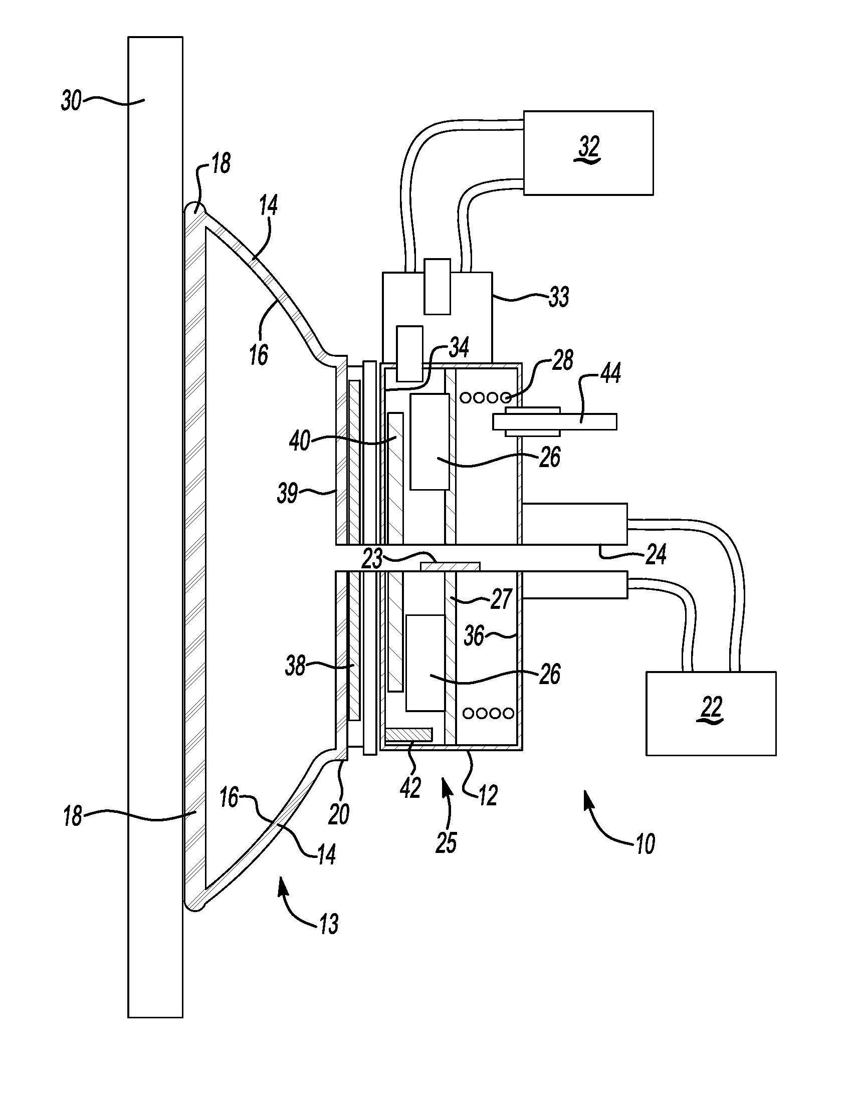
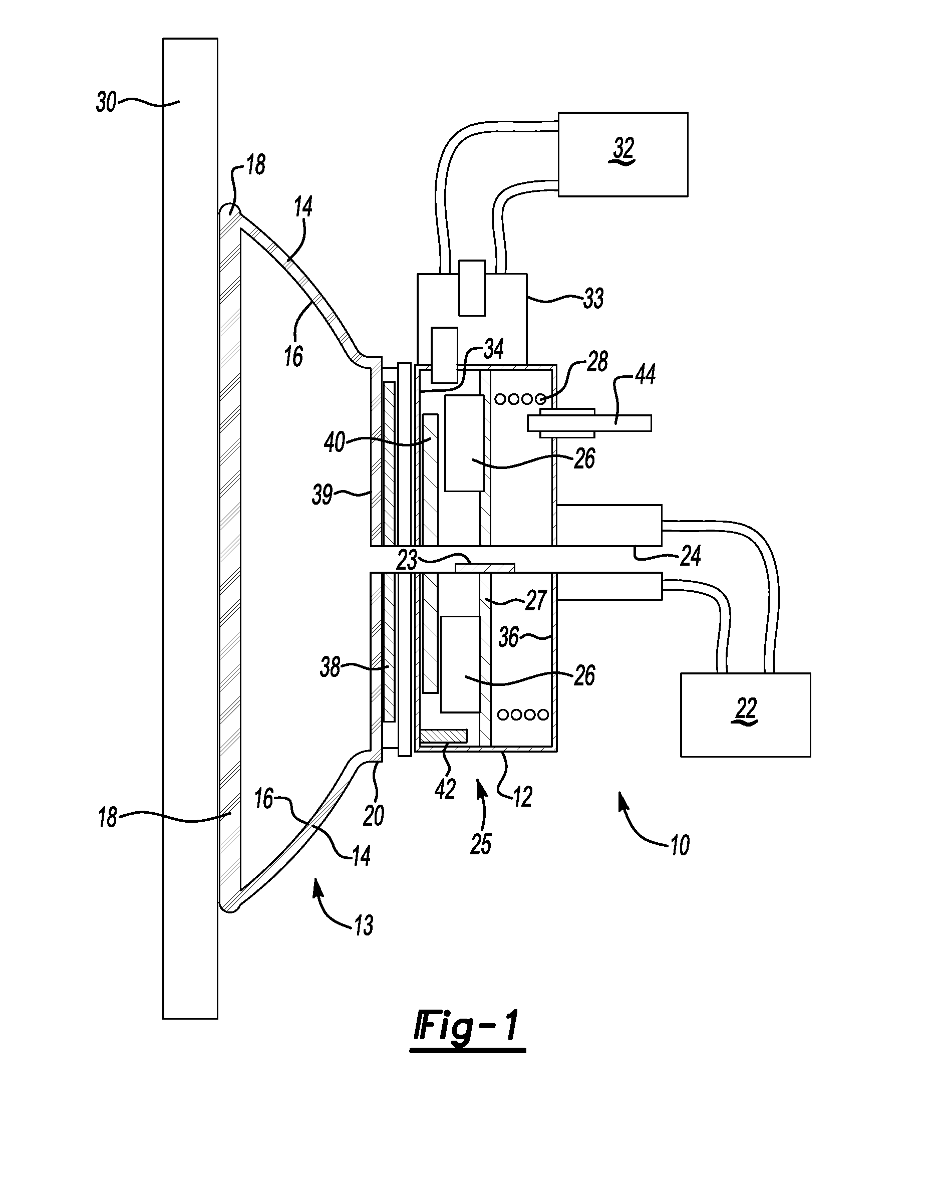
[0013]Referring to the drawings, wherein like reference numbers correspond to like or similar components throughout the several figures, there is shown in FIG. 1 a cross sectional view of a portion of one embodiment of an integrated releasable vacuum-magnetic gripper 10 (hereinafter referred to as integrated gripper 10).

[0014]A rigid housing 12 acts as a structural support for the integrated gripper 10, which has two gripper units: a vacuum gripper 13 and a magnetic gripper 25. As will be recognized by those having ordinary skill in the art, rigid housing 12 may be constructed of panels or sheets on a frame, or may be a unitary or integral structure.

[0015]Attached to the rigid housing 12 is a vacuum cup 14 which acts as the primary gripping device and flexible seal for the vacuum gripper 13 of integrated gripper 10. The vacuum cup 14 forms a vacuum cavity 16 which can be evacuated of air by a vacuum source 22. This creates a relative vacuum in vacuum cavity 16, which lifts a work pi...


PUM


Abstract

An integrated vacuum and magnetic gripper includes a rigid housing defining an internal chamber, and a flexible vacuum cup operatively connected thereto. A vacuum cavity is defined by the vacuum cup and a vacuum source is configured to reduce pressure in the vacuum cavity. A permanent magnet is disposed within the rigid housing, and a magnet release mechanism is configured to selectively render the magnet incapable of exerting sufficient force to hold the work piece. A pole plate may be interposed between the internal chamber and vacuum cavity, such that the pole plate forms a portion of the internal chamber and may act to provide friction on the work piece. A method of using the gripped includes operating at high acceleration while the vacuum gripper is monitored as fully operational and operating only at lower acceleration while the vacuum gripper is not fully operational.

Description

TECHNICAL FIELD[0001]This invention relates to devices and methods for lifting and transporting objects in industrial applications, such as for movement through assembly processes.BACKGROUND OF THE INVENTION[0002]Industrial manufacturing processes often include repetitive lifting and transportation of work pieces that are too heavy, too large, too fragile, or must be placed with too high precision to be lifted without mechanical assistance. The lifting and transportation of these work pieces may be accomplished manually or through automated means with material handling devices. Gripping devices allow heavy, large, and complex work pieces to be transported through manufacturing processes with increased reliability and efficiency.[0003]Vacuum-based grippers require backup mechanical clamps capable of maintaining control of the work piece or work pieces in the event of partial or total loss of vacuum pressure. Furthermore, vacuum grippers are capable of generating gripping force in onl...

Claims


Application Information

Patent Timeline
Patent Type & Authority Applications(United States)
IPC IPC(8): B66C1/02B66C1/04B66C1/06
CPCB66C1/0212B66C1/06B66C1/0256
Inventor WELLS, JAMES W.RANSOM, LANCE T.
Owner GM GLOBAL TECH OPERATIONS LLC
Why Eureka
Try Eureka