Receiver

a receiver and receiver technology, applied in the field of receivers, can solve the problems of uncontrollable gain and unreliable gain control of agc, and achieve the effect of accurate execution of demodulation processing

Inactive Publication Date: 2009-12-03
NIIGATA SEIMITSU +1
View PDF14 Cites 21 Cited by
  • Summary
  • Abstract
  • Description
  • Claims
  • Application Information

AI Technical Summary

Benefits of technology

[0019]According to the present invention having the structure described above, the gain of the high frequency amplifying circuit is controlled in such a manner that a signal having an excessively high level beyond a dynamic range of the A / D converting circuit is not input to the A / D converting circuit. Consequently, it is not necessary to provide a processing system in another route to prepare for the case in which a received signal having a high level is input, and two A / D converting circuits do not need to be provided. More specifically, it is possible to accurately execute the demodulation processing through the digital signal processing without providing the two A / D converting circuits.
[0020]According to the present invention, moreover, a gain is controlled by using both first control data generated by detecting a level of a signal in a broad band (including both a desirable wave and a disturbing wave) and second control data generated by detecting a level of a signal in a narrow band (only the desirable wave). Consequently, it is possible to properly control the gain of the AGC as a whole in consideration of both the signal level in the narrow band and the signal level in the broad band.

Problems solved by technology

For this reason, there is a problem in that two A / D converters are required for accurately executing the demodulation processing through the DSP.
For this reason, there is a problem in that a gain control considering a level of the disturbing wave is insufficient and the gain of the AGC is not always controlled properly.

Method used


Image

  • Receiver
  • Receiver
  • Receiver

Examples


first embodiment

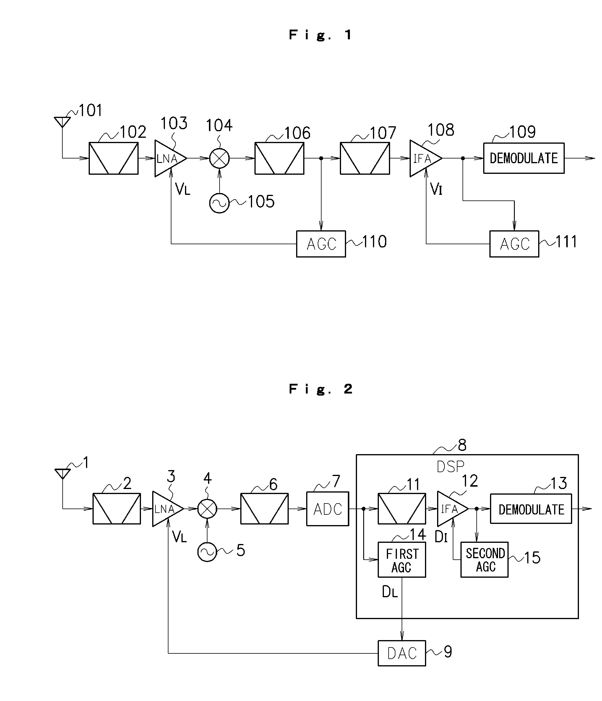
[0024]An embodiment according to the present invention will be described below with reference to the drawings. FIG. 2 is a diagram showing an example of a structure of a radio receiver according to a first embodiment. As shown in FIG. 2, the radio receiver according to the first embodiment includes an antenna 1, a band-pass filter 2, an LNA 3, a frequency mixing circuit 4, a local oscillating circuit 5, an antialiasing filter 6, an A / D converting circuit 7, a DSP 8, and a D / A converting circuit 9. These structures (excluding the antenna 1) are integrated in a single semiconductor chip through a CMOS (Complementary Metal Oxide Semiconductor) process, for example.

[0025]Moreover, the DSP 8 includes a band-pass filter 11 (corresponding to filter means according to the present invention), a digital IF amplifier 12 (corresponding to intermediate frequency amplifying means according to the present invention), demodulating means 13, first AGC means 14 (corresponding to first automatic gain ...

second embodiment

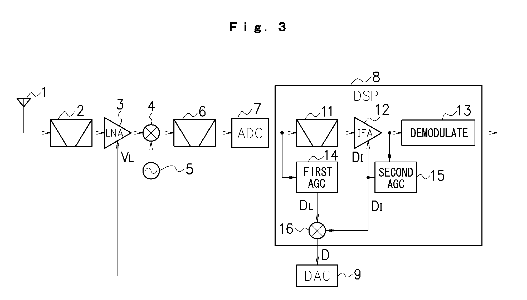
[0037]Next, a second embodiment according to the present invention will be described. FIG. 3 is a diagram showing an example of a structure of a radio receiver according to the second embodiment. In FIG. 3, portions having the same reference numerals as those shown in FIG. 2 have the same functions and repetitive description will be therefore omitted.

[0038]In the second embodiment, as shown in FIG. 3, a DSP 8 includes synthesizing means 16 as a functional structure to be implemented by a digital signal processing. The synthesizing means 16 synthesizes first control data DL output from first AGC means 14 and second control data DI output from second AGC means 15 to generate control data D, and supplies the control data D to a D / A converting circuit 9. Various methods can be applied to a synthesizing method. For example, it is also possible to add or multiply the first control data DL and the second control data DI. As a matter of course, the other calculations may be executed.

[0039]B...


PUM


Abstract

By A/D converting a signal output from a mixer (4) and inputting the A/D converted signal to a DSP (8), and generating AGC control data (DL) corresponding to a level of the signal to control a gain of an LNA (3) in such a manner that a voltage input to an A/D converting circuit (7) is lower than a full scale voltage of the A/D converting circuit (7), it is possible to prevent a signal having an excessively high level beyond a dynamic range of the A/D converting circuit (7) from being input to the A/D converting circuit (7). By controlling the gain of the LNA (3) corresponding to a level of a broad band signal before passing through a BPF (11) and controlling a gain of an IF amplifier (12) corresponding to a level of a narrow band signal after passing through the BPF (11), moreover, it is possible to properly control a gain of an AGC as a whole in consideration of signal levels of both a desirable wave and a disturbing wave.

Description

FIELD OF THE INVENTION[0001]The present invention relates to a receiver and more particularly to a receiver having an automatic gain control function for inhibiting a distortion of a signal from being occurred when the signal is input having a high level.DESCRIPTION OF THE RELATED ART[0002]In general, a wireless communication apparatus such as a radio receiver is provided with an AGC (Automatic Gain Control) circuit for controlling a gain of a received signal. FIG. 1 is a diagram showing a structure of a conventional radio receiver including an AGC circuit. As shown in FIG. 1, the conventional radio receiver includes an antenna 101, a band-pass filter 102, an LNA (Low Noise Amplifier) 103, a frequency mixing circuit 104, a local oscillating circuit 105, band-pass filters 106 and 107, an intermediate frequency amplifying circuit (IF amplifier) 108, a demodulating circuit 109, and AGC circuits 110 and 111.[0003]The band-pass filter 102 selectively outputs broadcast wave signals in a s...

Claims


Application Information

Patent Timeline
Patent Type & Authority Applications(United States)
IPC IPC(8): H04B1/16H04B1/26
CPCH04B1/001H03G3/3068
Inventor IKEDA, TAKESHIMIYAGI, HIROSHI
Owner NIIGATA SEIMITSU
Why Eureka
Try Eureka