Polylactide manufacturing apparatus and method for manufacturing polylactide

a technology of polybutylene terephthalate and manufacturing apparatus, which is applied in the direction of process and machine control, separation processes, instruments, etc., can solve the problems of limited use of exhaust gas treatment device disclosed in reference 1, deterioration in product quality, and lack of vacuum, so as to suppress the occurrence of plugging and corrosion, the vacuum degree is sufficien

Inactive Publication Date: 2009-12-03
HITACHI LTD
View PDF1 Cites 14 Cited by
  • Summary
  • Abstract
  • Description
  • Claims
  • Application Information

AI Technical Summary

Benefits of technology

[0013]In the present invention, solutions for driving the ejectors are transferred between the hot wells, in a direction from a latter stage to a front stage, whereby the concentration of lactic acid at the front stage is suppressed. Thus, a sufficient degree of vacuum is ensured and the occurrence of plugging and corrosion is suppressed.
[0014]According to the present invention, an exhausting gas treatment device can be realized in which plugging and corrosion resulting from polymerization of lactic acid, which is a raw material, can be suppressed in the production of polymers such as PLA (polylactide) through ring-opening polymerization and in which a sufficient degree of vacuum can be maintained even in a large plant.

Problems solved by technology

However, the use of the exhausting gas treatment device disclosed in Reference 1 is limited to the use for production of polybutylene terephthalate.
This in turn causes plugging in the exhausting gas treatment device, thereby causing a shortage of vacuum, whereby a polymerization reaction will not proceed.
Thus, the degree of polymerization could be insufficient, resulting in deterioration in the quality of products.

Method used


Image

  • Polylactide manufacturing apparatus and method for manufacturing polylactide
  • Polylactide manufacturing apparatus and method for manufacturing polylactide
  • Polylactide manufacturing apparatus and method for manufacturing polylactide

Examples


examples

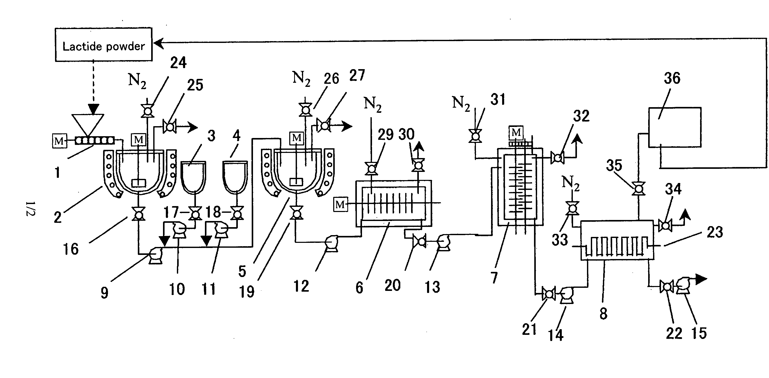
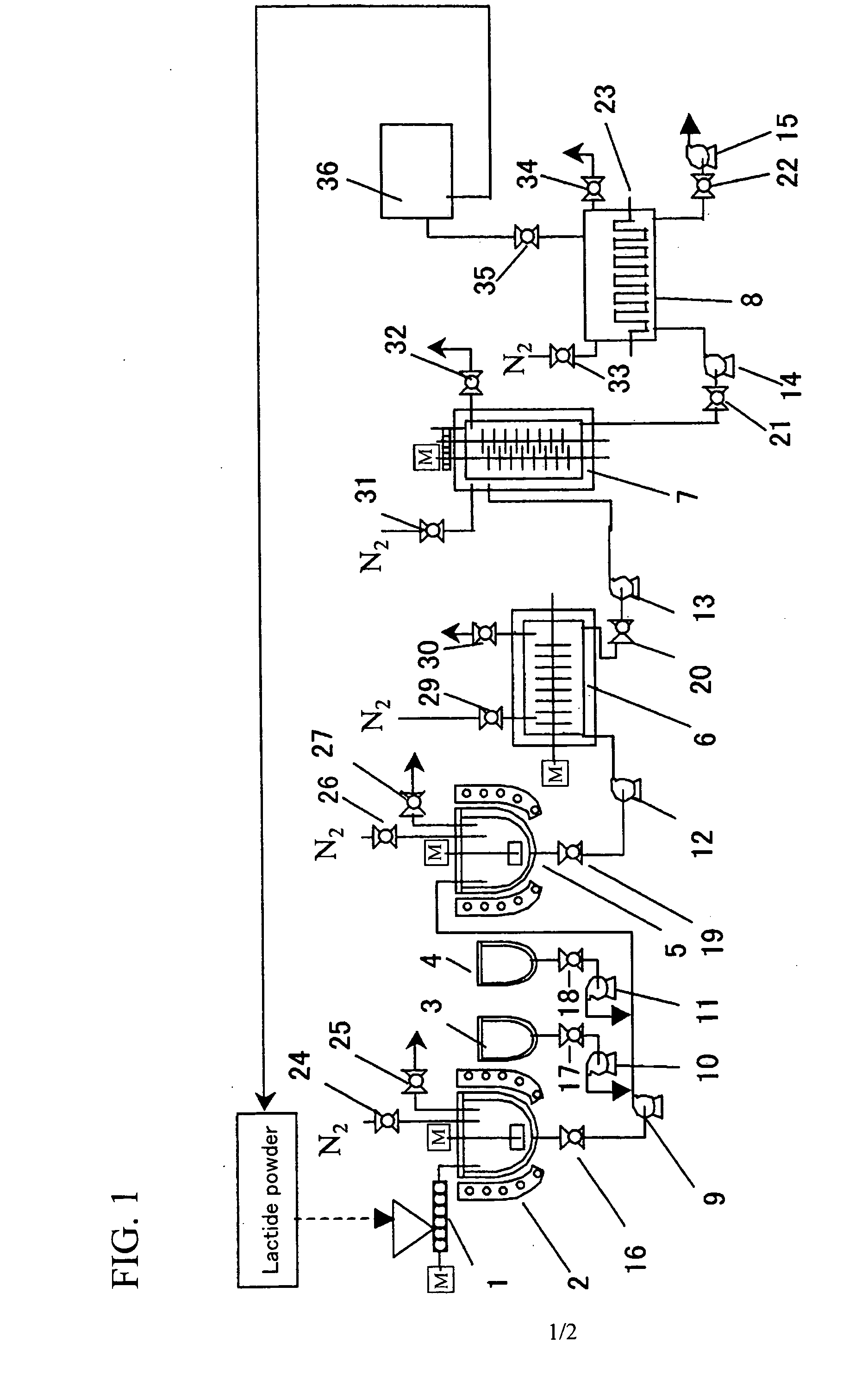
[0080]FIG. 1 illustrates the overall structure of an example of a polylactide manufacturing apparatus and a method for manufacturing polylactide in accordance with the present invention. In this example, polymerization for producing polylactide is carried out with an apparatus including a lactide supply device 1, a lactide melting device 2, a catalyst supply device 3, a polymerization initiator supply device 4, a lactide supply device 5, a horizontal reaction vessel 6, a vertical reaction vessel 7, a volatilizer 8, liquid transfer pumps 9-15, and valves 16-22. This example illustrates a case in which a reaction device includes two tanks that are the horizontal reaction vessel 6 and the vertical reaction vessel 7 connected in series, and unreacted lactide is removed using the volatilizer 8. Part of the liquid transfer pumps 9-15 can be omitted if a liquid to be transported has low viscosity and can thus be transported with the use of the gravity of the liquid. Part of the valves 16-2...


PUM

PropertyMeasurementUnit
temperatureaaaaaaaaaa

Abstract

In a process of manufacturing polylactide, synthesis of high-quality polymers is achieved with a sufficient degree of vacuum secured. Provided is an apparatus for manufacturing polylactide which includes the steps of preparing lactide through oligomerization of lactic acid and depolymerization of the resulting oligomers, effecting ring-opening polymerization of the lactide, and removing unreacted lactide. The apparatus comprises an exhausting gas treatment device for reducing pressure in the step of removing unreacted lactide. The exhausting gas treatment device includes boilers (81-83) for generating water vapor; a pressure-reducing section having stages each including an ejector (71-73) driven with the water vapor, a condenser (61-63) connected downstream of the ejector, and a hot well tank (41-43) connected to the condenser; and a main condenser 60 and a main hot well tank 40 connected to the main condenser that are disposed on a pipe line through which a gas of the unreacted lactide is suctioned into the pressure-reducing section. The gas of the unreacted lactide is washed away in the main condenser using a liquid containing lactic acid as a main component that has been collected in the main hot well tank.

Description

BACKGROUND OF THE INVENTION[0001]1. Field of the Invention[0002]The present invention relates to a method and apparatus for removing unreacted monomers and unreacted lactide (dimers of lactic acid) from polylactide.[0003]2. Background Art[0004]For removing unreacted substances from polylactide, it has become increasingly difficult, with an increase in size of plants, to ensure the degree of vacuum that is required for removing such unreacted substances with the use of a prior-art vacuum pump alone.[0005]In addition, during a vacuum suction time, a problem may arise that condensation products such as lactic acid monomers or lactide would scatter in an exhausting gas treatment device, which could cause plugging or corrosion.[0006]Polylactide, which is one type of polymers synthesized by a ring-opening polymerization reaction, is polyester that is transparent and colorless and is produced from lactic acid, which is one of hydroxycarboxylic acids, as a raw material. Among methods of syn...

Claims


Application Information

Patent Timeline
Patent Type & Authority Applications(United States)
IPC IPC(8): C08F2/01B01J19/24
CPCB01J19/1818C08G63/08B01J2219/00006
Inventor OKA, KENICHIROMATSUO, TOSHIAKIKAMIKAWA, MASAYUKIOKAMOTO, NARUYASU
Owner HITACHI LTD
Why Eureka
Try Eureka