Method and Device for Regulating the Operating Line of a Gas Turbine Combustion Chamber
What is AI technical title?
AI technical title is built by Patsnap AI team. It summarizes the technical point description of the patent document.
a technology of operating line and gas turbine combustion chamber, which is applied in the direction of combustion failure, lighting and heating apparatus, instruments, etc., can solve the problems of reducing the service life of the combustion chamber and shortening the maintenance interval, pilot gas mass flow cannot be below or above certain limits, and time-consuming resetting or subsequent setting of the pilot gas curve, so as to prevent flame instabilities
Active Publication Date: 2009-12-10
SIEMENS ENERGY GLOBAL GMBH & CO KG
View PDF15 Cites 24 Cited by
Summary
Abstract
Description
Claims
Application Information
AI Technical Summary
This helps you quickly interpret patents by identifying the three key elements:
Problems solved by technology
Method used
Benefits of technology
Benefits of technology
[0009]The object of the present invention is therefore to provide a regulating method and regulating device, which can advantageously be deployed to prevent flame instabilities.
[0012]The inventive regulating method allows the flame to be kept stable without the influence of the influencing variables on flame stability having to be known precisely from a quantitative standpoint.
[0020]If characteristic quantities, formed from the absolute values of the mean autocorrelations and their transients as well as optionally also from the variances and transients of the variances of the autocorrelations, exceed specific values, a regulating intervention takes place, for example reduction of output or change in quantity of pilot gas. Significantly longer prior warning periods can be achieved by analyzing transients.
[0024]The link between the captured controlled variable and the reference variable on the one hand and the manipulated variable on the other hand can in particular be made on the basis of a fuzzy logic. Alternatively however it is also possible to use a neural network or a fixed rule system. Fuzzy logic in particular allows a graduated response to be achieved as a function of the degree of approach to burner stability limits.
[0025]Generally the inventive regulating method makes it possible to prevent the burner stability limits being reached and exceeded in a reliable manner. Emergency tripping of the gas turbine plant, in other words rapid shutdown of the plant, because the burner stability limits have been reached, can thus be reliably avoided. Also the operating limits of the gas turbine plant can be better utilized. For example a high nitrogenoxide emission due to a high level of flame instability can be reduced or a higher corrected waste gas temperature (OTC Outlet Temperature Corrected) can be used, thereby improving the efficiency of the gas turbine plant. It is also possible to prevent or at least reduce a drop in the corrected waste gas temperature when the compressor intake temperature is below the temperature specified for this purpose. The compressor intake temperature here refers to the temperature of the air taken in by the compressor as it enters the compressor.
[0031]The inventive method can be implemented with the inventive regulating device, thereby optimizing the operating line of the gas turbine plant, in particular by better prevention of flame instabilities.
Problems solved by technology
Flame instabilities occur in particular due to resonant combustion vibration in the combustion waste gas and can lead on the one hand to increased pollutant emission and on the other hand to vibration of the combustion chamber, reducing the service life of the combustion chamber and shortening maintenance intervals.
In this process the pilot gas mass flow cannot be below or above certain limits, since the flame would otherwise enter a non-stable range.
This may result in a time-consuming resetting or subsequent setting of the pilot gas curve being required.
The setting process incurs high costs and long outage times.
In addition the influence of the influencing variables on the pilot gas curve is not adequately known from a quantitative standpoint.
It is generally not possible to respond appropriately to some influencing variables.
Method used
Image
Click on the blue label to locate the original text in one second.
Reading with bidirectional positioning of images and text.
Examples
Embodiment Construction
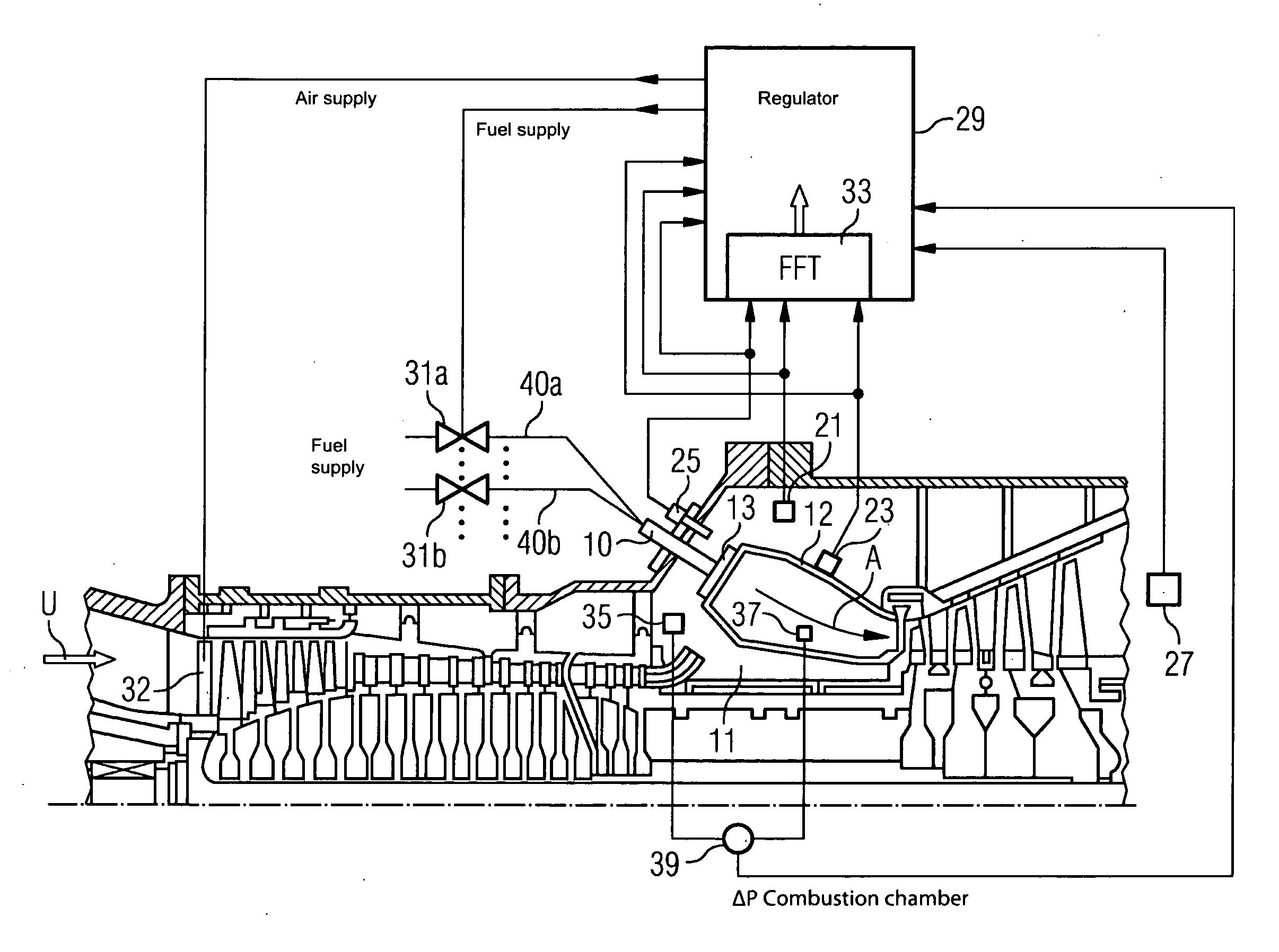
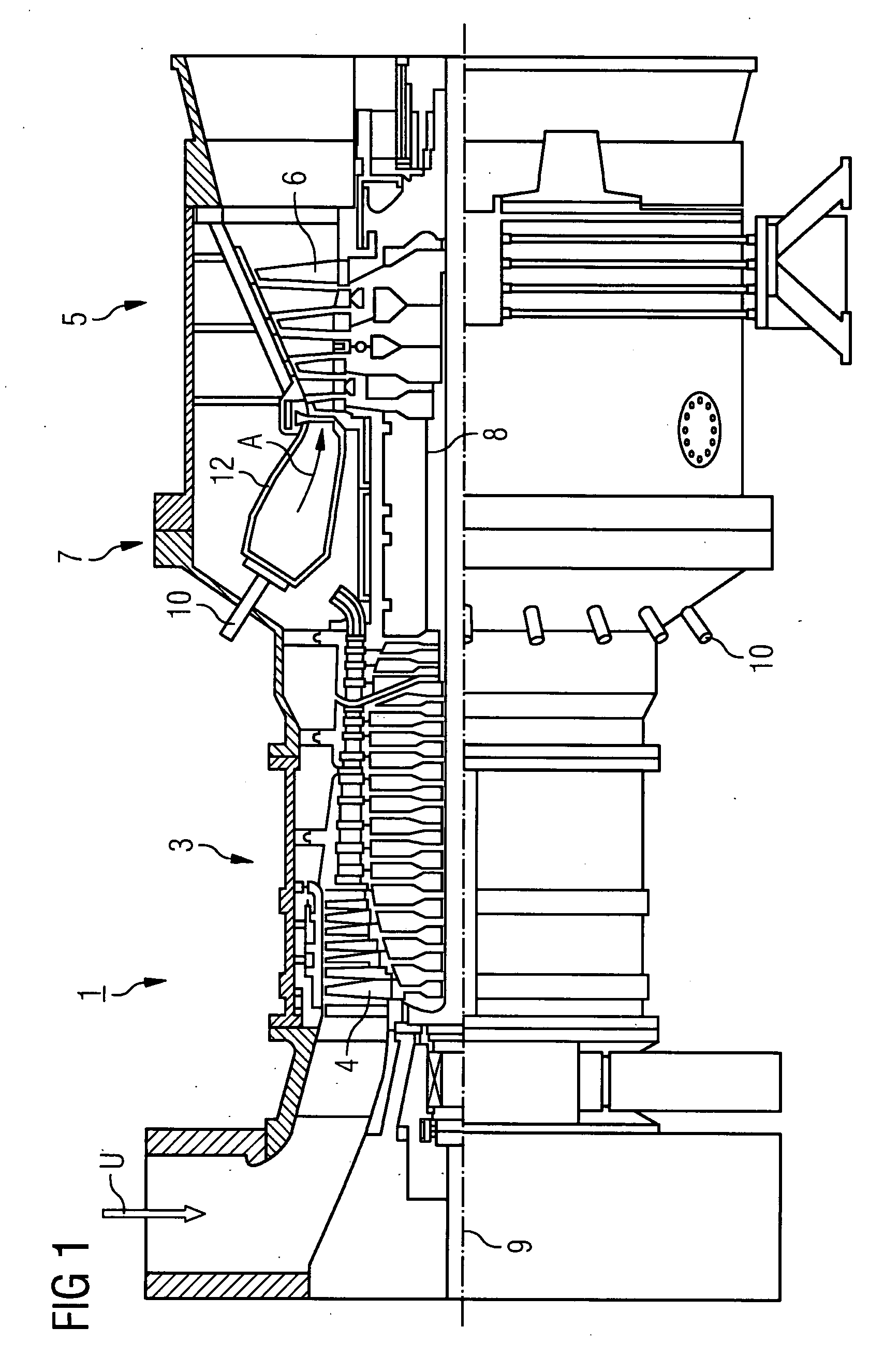
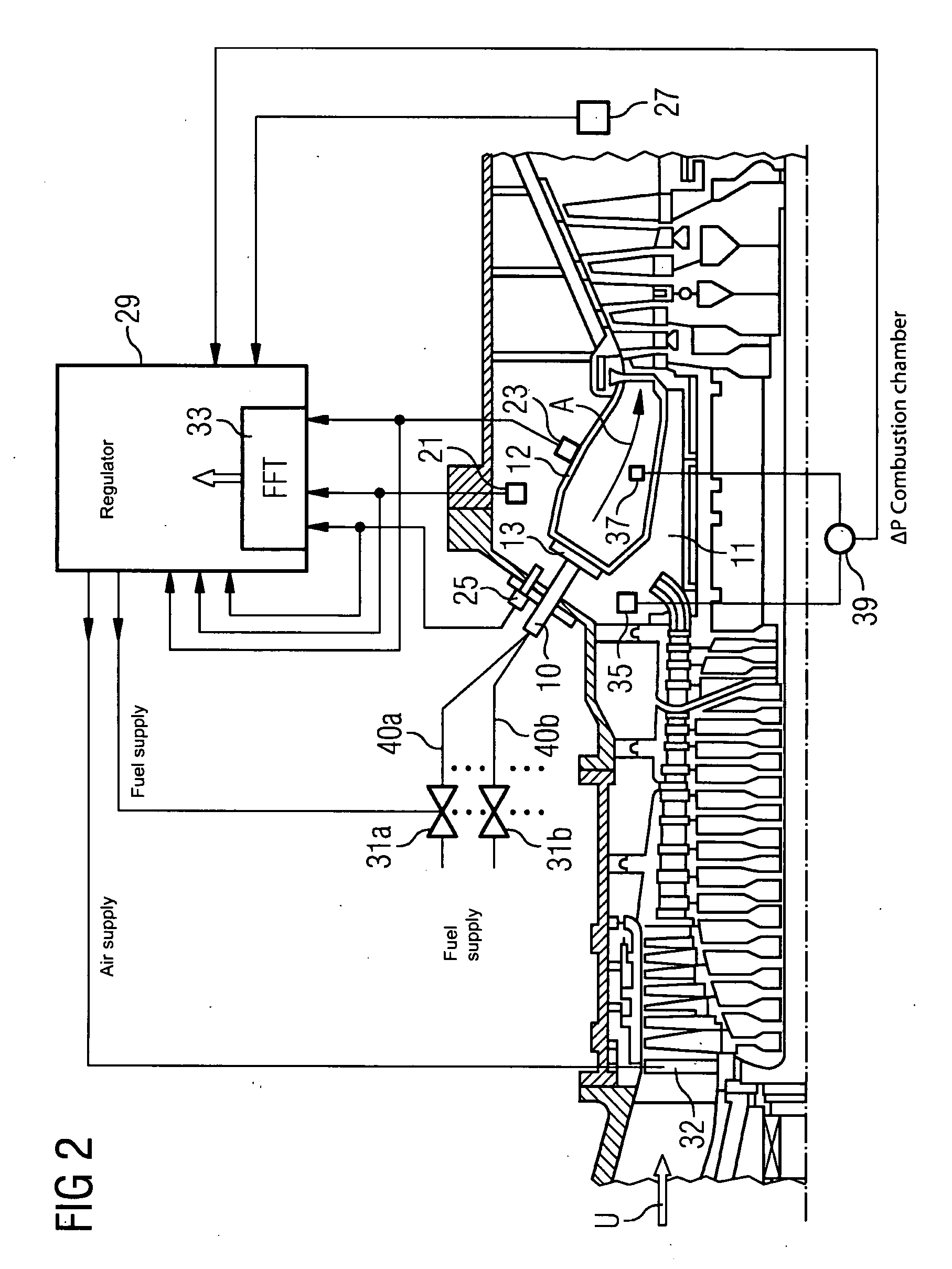
[0039]FIG. 1 shows a partial section of a side view of a gas turbine plant 1. It comprises a compressor section 3, a turbine section 5 and a burner section 7. In the compressor section 3 and in the turbine section 5 compressor blades 4 or turbine blades 6 are disposed on a common shaft 8, also referred to as a turbine rotor. The turbine rotor 8 is supported in such a manner that it can rotate about a central axis 9.
[0040]The burner section 7 comprises a number of burners 10, which open into a combustion chamber 12, which in turn opens into the turbine section 5. The combustion chamber 12 in the present exemplary embodiment is configured as an annular combustion chamber, in other words it extends in a circular manner around the turbine rotor 8.
[0041]During operation of the gas turbine plant 1 ambient air U is taken in by way of the compressor, compressed to a higher pressure and output into the burner section 7 as so-called compressor air. The size of the air mass flow entering the c...
PUM
Abstract
A regulating device for regulating the course of a gas turbineplant has at least one sensor for sensing a measurement variable and for outputting a measurement signal which represents the measurement variable; at least one adjusting system for influencing air and / or fuel supply to a combustion chamber of the gas turbineplant on the basis of a correcting variable; and a regulator connected to the at least one sensor so as to receive the measurement variable and to the at least one adjusting system for outputting the correcting variable, the regulator being designed to determine the correcting variable on the basis of the measurement variable received and its deviation from a pilot variable. At least one sensor is designed to sense the variation in time of at least one burner or combustion chamber parameter as measurement variable.
Description
CROSS REFERENCE TO RELATED APPLICATIONS[0001]This application is the US National Stage of International Application No. PCT / EP2006 / 062183, filed May 10, 2006 and claims the benefit thereof. The International Application claims the benefits of European application No. 05010543.6 filed May 13, 2005, both of the applications are incorporated by reference herein in their entirety.FIELD OF INVENTION[0002]The present invention relates to a regulating method and a regulating device for regulating the operating line of a gas turbinecombustion chamber.BACKGROUND OF THE INVENTION[0003]A gas turbine is a flow machine, which generally comprises a compressor, turbine and combustion chamber section. In the compressor ambient air that has been taken in is compressed and the compressed air is then supplied to the combustion chamber section. At least one combustion chamber with at most a number of burners is disposed in the combustion chamber section, to which burners the compressed air is supplied...
Claims
Application Information
Patent Timeline
Application Date:The date an application was filed.
Publication Date:The date a patent or application was officially published.
First Publication Date:The earliest publication date of a patent with the same application number.
Issue Date:Publication date of the patent grant document.
PCT Entry Date:The Entry date of PCT National Phase.
Estimated Expiry Date:The statutory expiry date of a patent right according to the Patent Law, and it is the longest term of protection that the patent right can achieve without the termination of the patent right due to other reasons(Term extension factor has been taken into account ).
Invalid Date:Actual expiry date is based on effective date or publication date of legal transaction data of invalid patent.
Patent Type & AuthorityApplications(United States)

