

Engine and Power Transmission Device
- Summary
- Abstract
- Description
- Claims
- Application Information
AI Technical Summary
Benefits of technology
Problems solved by technology
Method used
Image

Examples
first embodiment
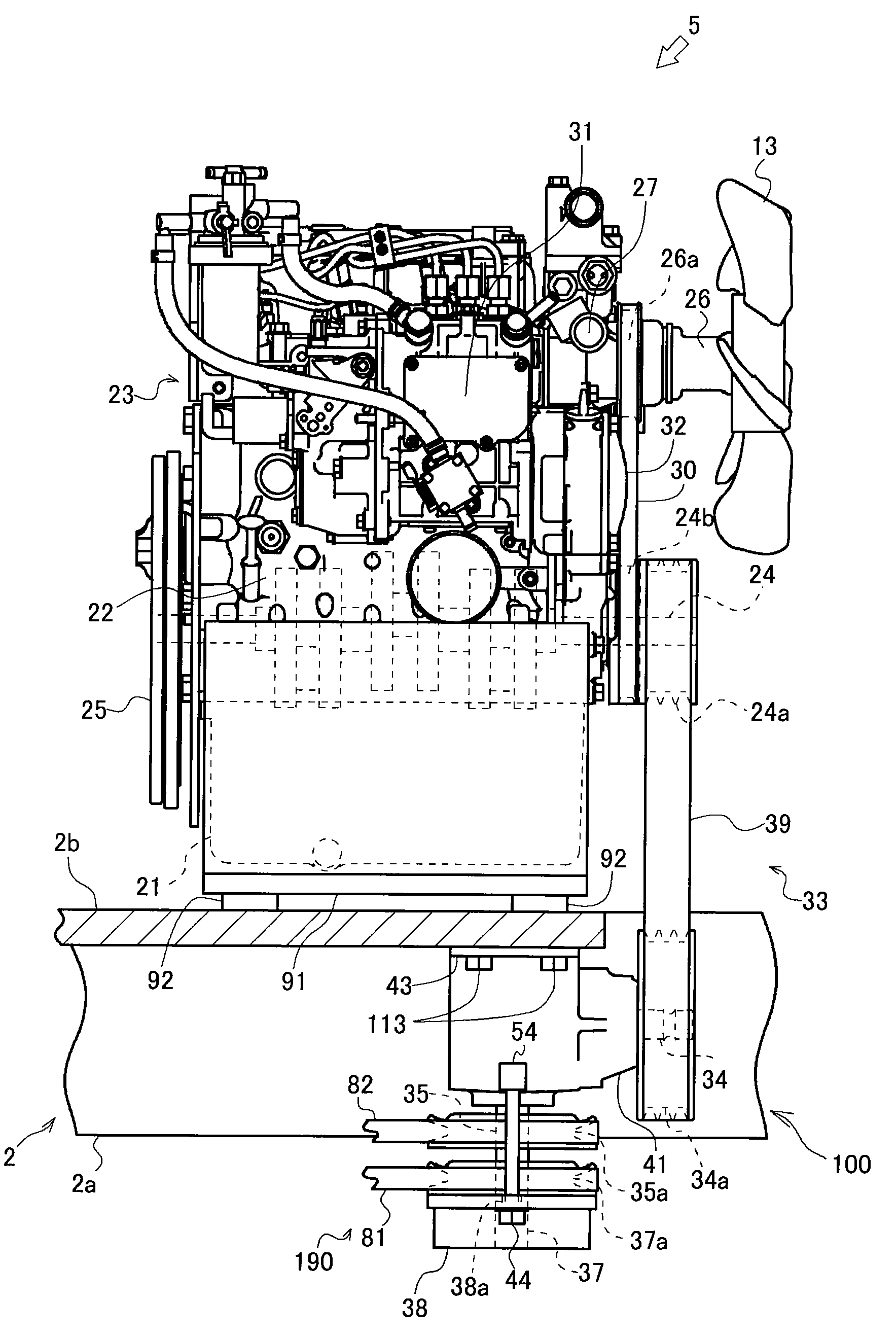
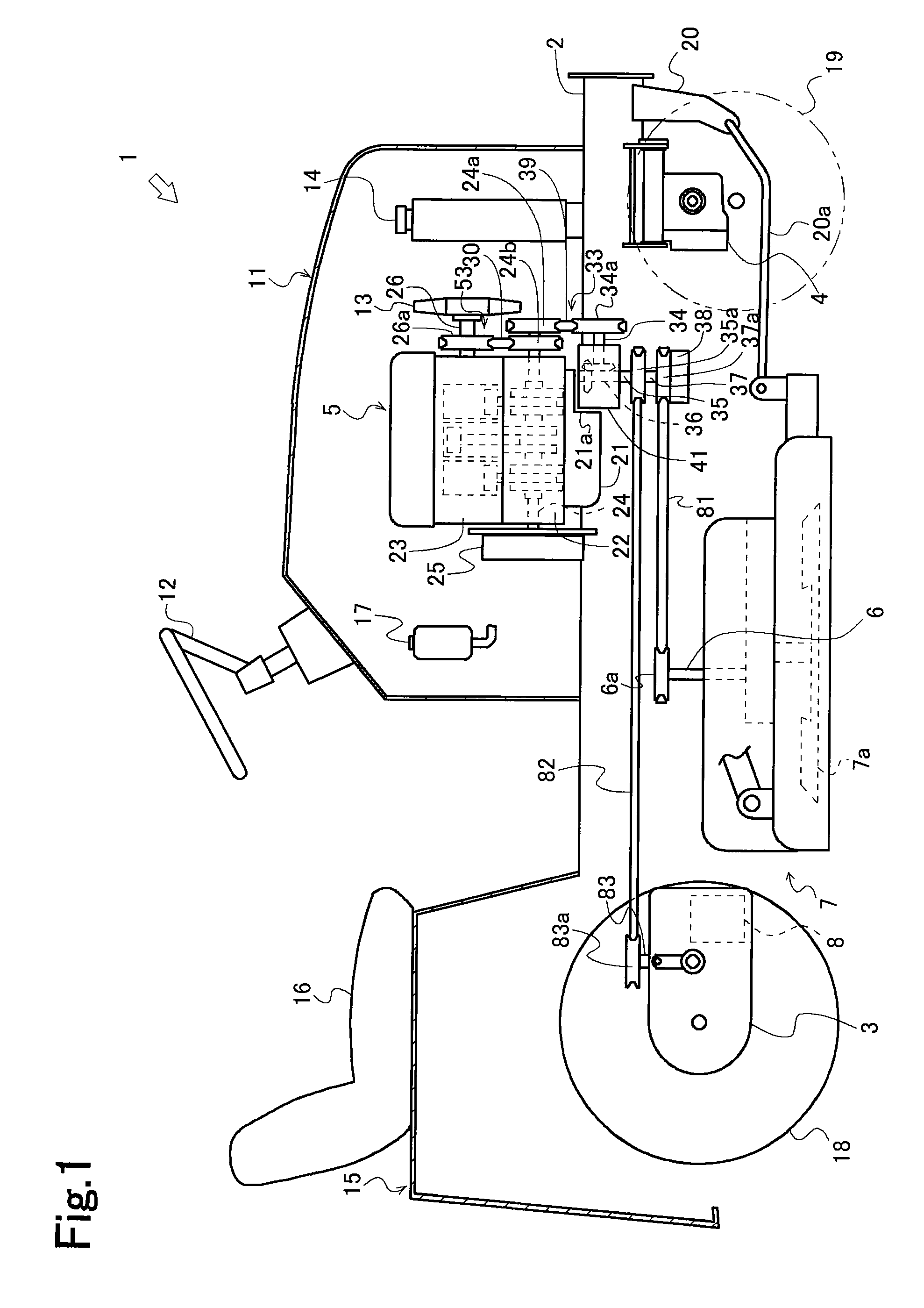
[0092]An entire configuration of a work vehicle 1 provided with an engine 5 according to the present invention. Referring to FIG. 1, the work vehicle 1 is an Ackerman steering lawnmower, and the work vehicle 1 includes a vehicle frame 2, a rear axle drive device 3 which is supported in a rear portion of the vehicle frame 2, a front axle support device 4 which is supported in a front portion of the vehicle frame 2, the engine 5 which is supported by the vehicle frame 2 between the rear axle drive device 3 and the front axle support device 4, and a mower 7 which is suspended below the vehicle frame 2 while being able to be moved up and down.
[0093]A hydraulic motor 8 is accommodated in the rear axle drive device 3, and the hydraulic motor 8 is liquid-connected to a hydraulic pump (not shown) while being able to be driven by the hydraulic pump.
[0094]The engine 5 is accommodated in a hood 11, a steering wheel 12 is extended above and behind from a dashboard located immediately behind the...
second embodiment
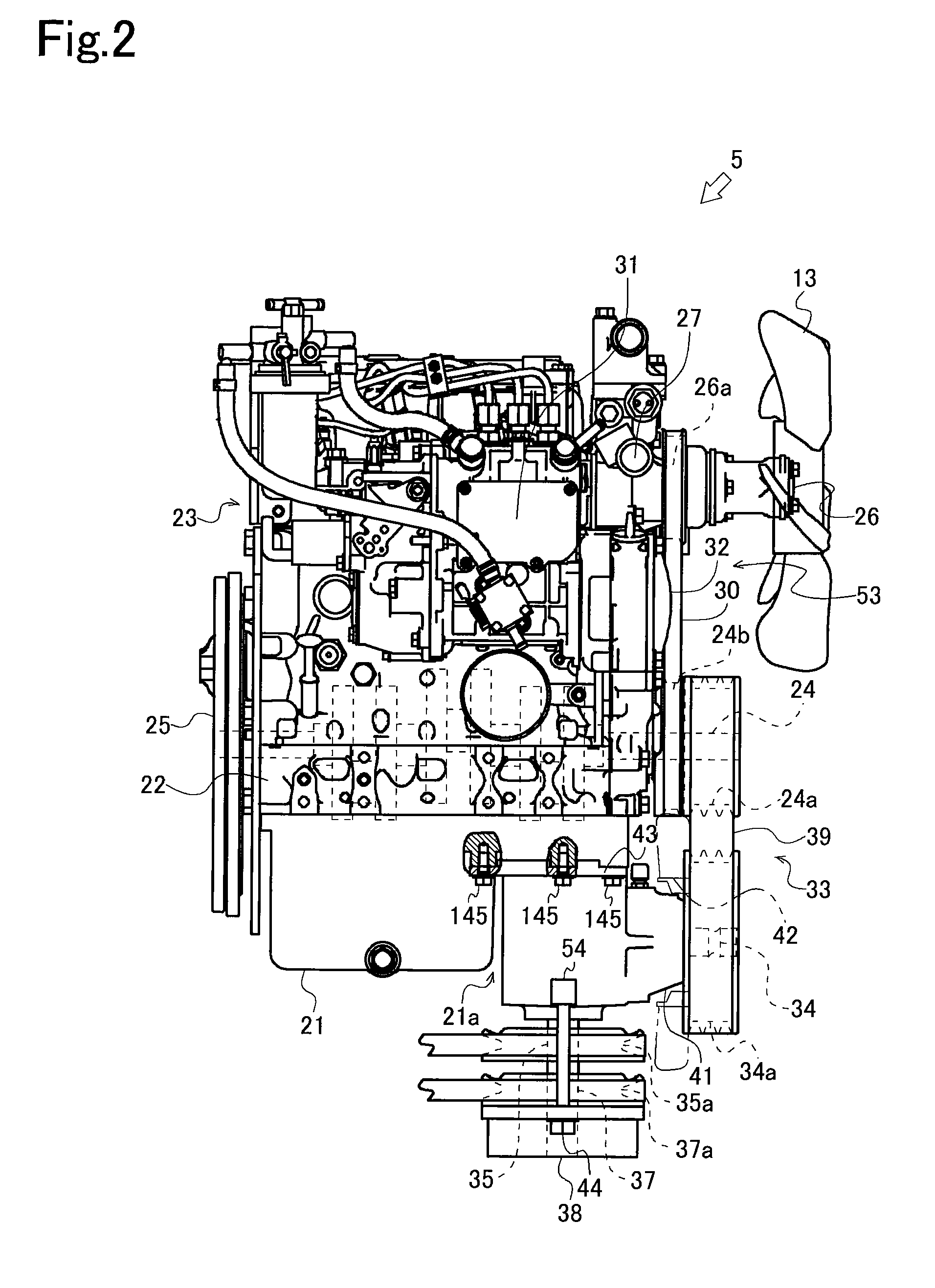
[0128]An engine 5 according to the present invention will be described with reference to FIGS. 10 to 12.
[0129]Referring to FIG. 10 to 12, in the engine 5 of the second embodiment, using bolts 245 having a length from the lower surface of the attaching portion 43 to the cylinder block 22, the gearbox 41 is attached to the cylinder block 22 while fastened along with the oil pan 21. On right and left sides in the lower surface of the oil pan 21 in the notch 21a, bolt holes 246 are made at positions overlapping the bolt holes 43a of the attaching portion 43 in the planar view. The bolt hole 246 pierces upward through the oil pan 21 from the lower surface of the oil pan 21 to the cylinder block 22. On right and left sides of the cylinder block 22, bolt holes 247 are made at positions overlapping the bolt hole 246 of the oil pan 21 in the planar view.
[0130]In the above-described configuration, the gearbox 41 is disposed in the notch 21a, and the bolts 245 are screwed from below the bolt h...
third embodiment
[0132]An engine 5 according to the present invention will be described with reference to FIGS. 13 and 14.
[0133]Referring to FIGS. 13 and 14, in the engine 5 of the third embodiment, the gearbox 41 is disposed in a front lower corner portion of the oil pan 21, and the oil pan 21 and the gearbox 41 are integrally molded. An inside of the oil pan 21 and an inside of the gearbox 41 are partitioned by a partition wall 50 to prevent the oil from flowing into the gearbox 41 from the oil pan 21.
[0134]Thus, in the engine 5 of the third embodiment of the present invention, the oil pan 21 is provided in the lower portion of the engine 5, and the oil pan 21 and the gearbox 41 are integrally molded. The gearbox 41 and the oil pan 21 can integrally be formed to neglect the attaching work of the gearbox 41. Therefore, the number of components is decreased while the efficiency of the attaching work is improved, so that the cost reduction can easily be achieved. The gearbox 41 becomes the same vibra...
PUM
 Abstract
Description
Claims
Application Information