Production of Blended Fuel from Renewable Feedstocks

a technology of renewable feedstocks and blended fuels, applied in biofuels, fuels, hydrocarbon oils treatment products, etc., can solve the problems of deactivation of isomerization catalysts, and achieve the effect of reducing the amount of diesel in the first reaction zone and minimizing the number of cracking events per molecul

Active Publication Date: 2009-12-10
UOP LLC
View PDF82 Cites 145 Cited by
  • Summary
  • Abstract
  • Description
  • Claims
  • Application Information

AI Technical Summary

Benefits of technology

[0016]The portion of the process which provides the paraffin rich component comprises treating the feedstock in a reaction zone by hydrogenating and deoxygenating the feedstock at reaction conditions to provide a first reaction zone product comprising n-paraffins. The carbon dioxide and water generated as byproducts in the first reaction zone are selectively removed from the first reaction product in an integrated hot high pressure stripper using hydrogen as the stripping gas. A diesel range stream, an aviation range stream, a naphtha / gasoline range stream, a naphtha / gasoline and LPG range stream or any mixture thereof may be optionally used as a rectification agent in the selective hot high pressure hydrogen stripper to decrease the amount of first reaction zone diesel and aviation range product carried in the overhead of the selective hot high pressure hydrogen stripper. Note that the naphtha / gasoline range stream is within the boiling point range for gasoline and therefore may also be considered a gasoline boiling point range stream. The hydrogen stripped first reaction zone product is introduced to a hydroisomerization and selective cracking reaction zone. The selective hydrocracking allows for aviation fuel range products, if desired, by preferentially cracking C1 to C6 fragments off the end of the longer chain paraffins and by minimizing the number of cracking events per molecule. The desired product, at least one paraffin rich component in the diesel boiling point range, the aviation boiling point range, and or the naphthene boiling range product, is recovered.

Problems solved by technology

The presence of oxygen containing molecules including water, carbon dioxide, and other carbon oxides may result in the deactivation of the isomerization catalyst.

Method used


Image

  • Production of Blended Fuel from Renewable Feedstocks
  • Production of Blended Fuel from Renewable Feedstocks
  • Production of Blended Fuel from Renewable Feedstocks

Examples


Embodiment Construction

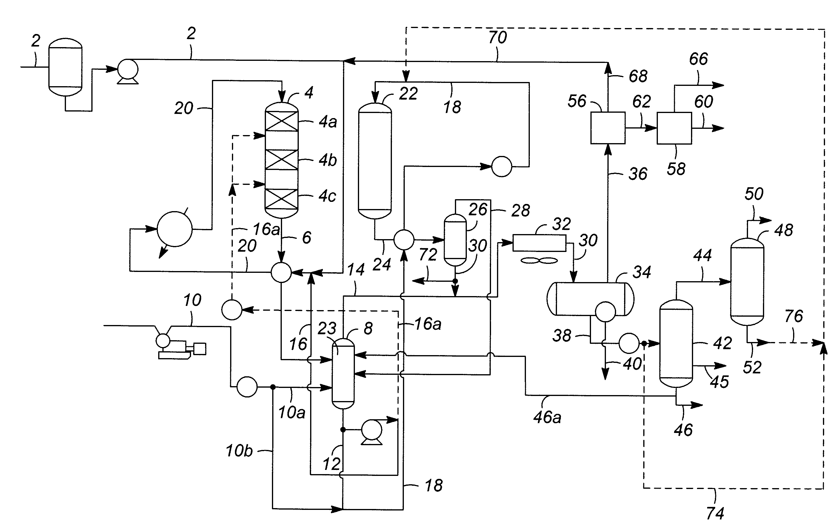
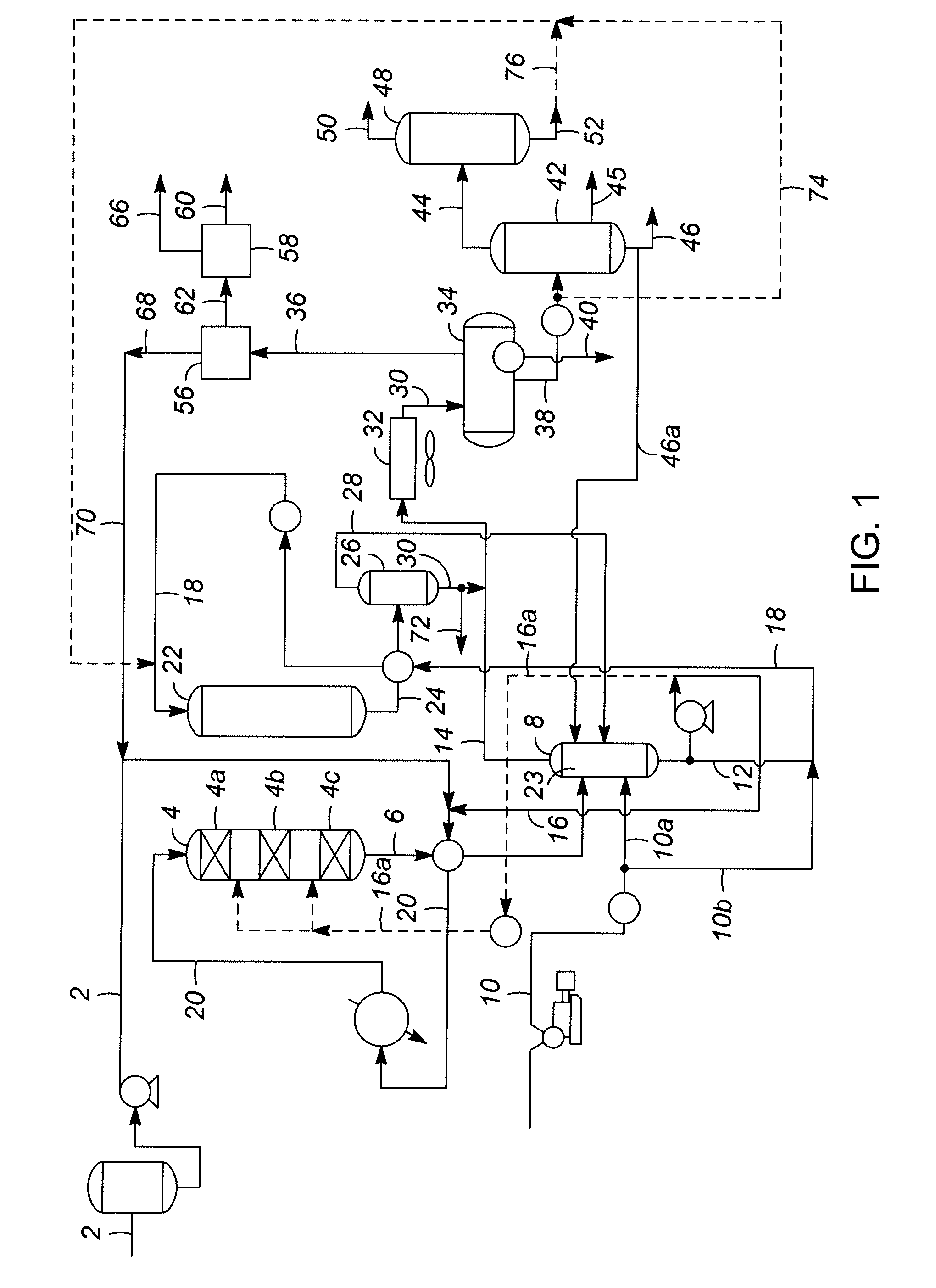
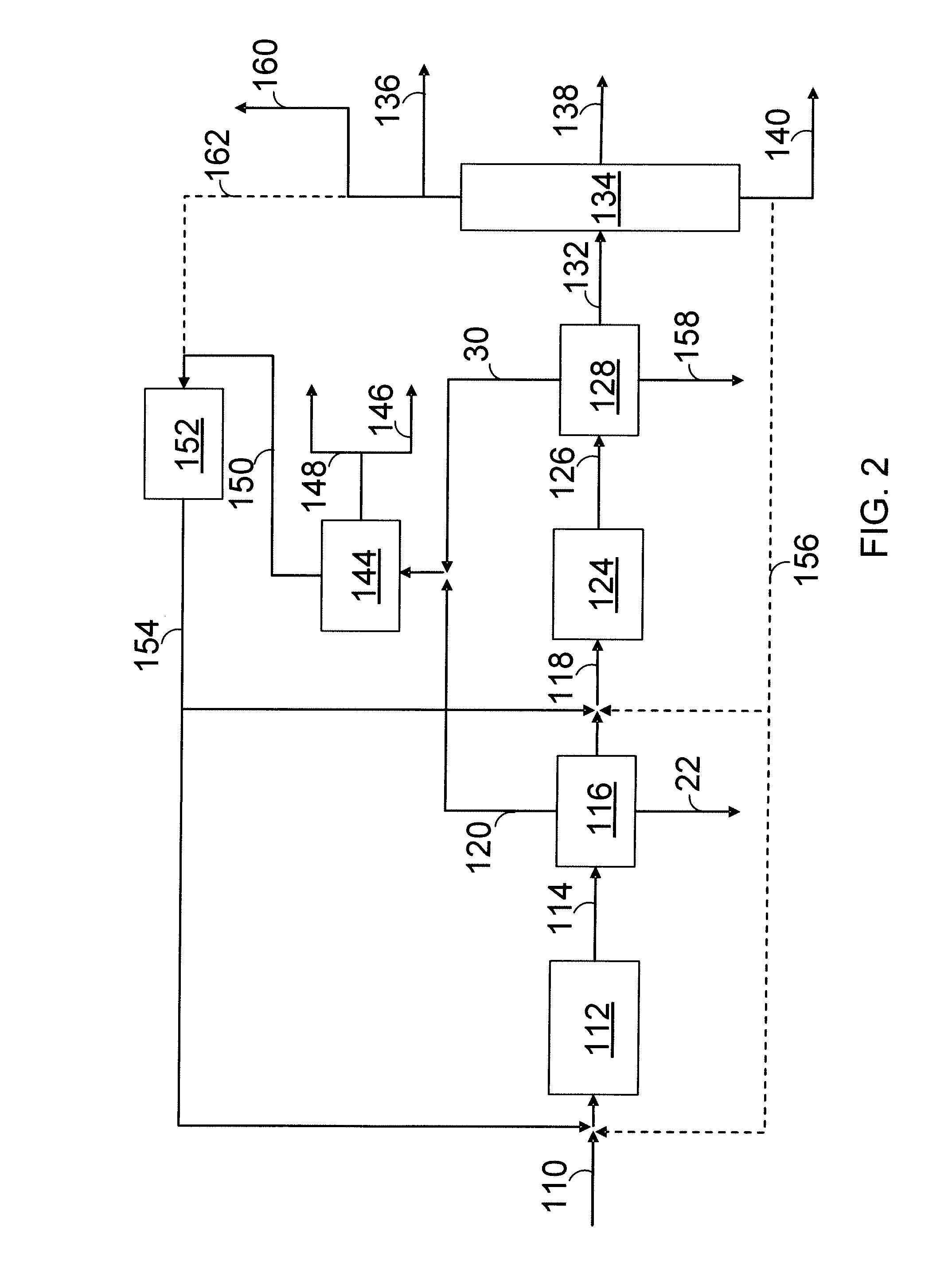
[0023]The invention provides a process for generating at least one paraffin rich component from a renewable feedstock and at least one cyclic rich component from a renewable feedstock, and blending at least those two components to provide a blended fuel.

Generating the Paraffin Rich Component

[0024]The paraffin rich component may be one or more hydrocarbon streams, a diesel boiling point range product, an aviation boiling point range product, and a naphtha / gasoline boiling point range product from renewable feedstocks such as feedstocks originating from plants or animals. The term “rich” is meant to indicate at least 40 mass-%. The term renewable feedstock is meant to include feedstocks other than those obtained from petroleum crude oil. Another term that has been used to describe members of this class of feedstock is biorenewable fats and oils. The renewable feedstocks that can be used to generate the paraffin rich component include any of those which comprise glycerides and free fat...


PUM

PropertyMeasurementUnit
pressureaaaaaaaaaa
temperatureaaaaaaaaaa

Abstract

A process for producing a blended fuel from a paraffin rich component and a cyclic rich component, where each of the components are generated from a renewable feedstock, is presented. The paraffin rich component is generated from glycerides and free fatty acids in feedstocks such as plant and animal oils. The cyclic rich component is generated from biomass derived pyrolysis oil. The source of the animal or plant oil and the biomass may be the same renewable source.

Description

CROSS-REFERENCE TO RELATED APPLICATION[0001]This application claims priority from Provisional Application Ser. No. 61 / 042,747 filed Apr. 6, 2008, the contents of which are hereby incorporated by reference in its entirety.STATEMENT REGARDING FEDERALLY SPONSORED RESEARCH OR DEVELOPMENT[0002]This invention was made under the support of the United States Government, United States Army Research Office, with financial support from DARPA, Agreement Number W911NF-07-C-0049. The United States Government has certain rights in the invention.BACKGROUND OF THE INVENTION[0003]The process produces one or more blended fuels from renewable feedstocks including biomass derived pyrolysis oil and the triglycerides and free fatty acids found in plant and animal oils fats and greases. At least one paraffin rich component is produced from the triglycerides and free fatty acids found in plant and animal oils fats and greases while at least one cyclic rich component is produced from a biomass derived pyroly...

Claims


Application Information

Patent Timeline
Patent Type & Authority Applications(United States)
IPC IPC(8): C10L1/04C10G45/00
CPCC10G45/58C10G2300/80C10L1/06C10L1/08Y02E50/13Y02T50/678C10G2300/1037C10G3/46C10G3/47C10G3/49C10G3/50C10G2300/1014C10G2300/1018C10G2300/1022C10G2300/4081C10G2400/02C10G2400/04C10G2400/08C10L1/04Y02P30/20Y02E50/10
Inventor BRANDVOLD, TIMOTHY A.MCCALL, MICHAEL J.
Owner UOP LLC
Why Eureka
Try Eureka