Brushless motor apparatus and method

a brushless motor and motor body technology, applied in the direction of electrical apparatus, dynamo-electric machines, supports/enclosements/casings, etc., can solve the problem of low open space to solid material ratio in the winding core compared to conventional practice, and achieve the effect of effectively pushing the air, improving heat transfer, and improving performan

Inactive Publication Date: 2009-12-10
HOFFMAN LESLIE
View PDF0 Cites 11 Cited by
  • Summary
  • Abstract
  • Description
  • Claims
  • Application Information

AI Technical Summary

Benefits of technology

[0007]Several other features also contribute to improving heat transfer away from the wire coils, thereby improving performance. The end bells enclosing the winding core at both ends are open. The rotor end bell has deep blades, effectively pushing the air like a fan as the shaft rotates. The mounting end bell includes skeletal struts that reduce resistance to air flow, both axially and radially. The openings through the winding core and the end bells combine to facilitate axial air flow to cool the conducting material in the single layer of wire.
[0008]The rotating components are supported by a very low profile collection of bearings. The overall design structure and construction techniques permit sustained dissipation of heat and remarkable efficiency at all power settings in a lightweight assembly.

Problems solved by technology

Because of the combination of these two aspects, the ratio of open space to solid material in the winding core is low compared to conventional practice.

Method used


Image

  • Brushless motor apparatus and method
  • Brushless motor apparatus and method
  • Brushless motor apparatus and method

Examples


Embodiment Construction

[0017]The figures and associated text illustrate exemplary embodiments, which are not intended to be comprehensive of the scope of the invention. A person of ordinary skill in the art will recognize many embodiments of the inventive concept that are not explicitly detailed here.

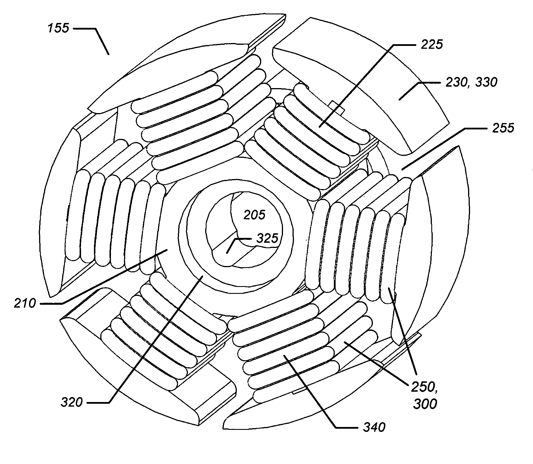
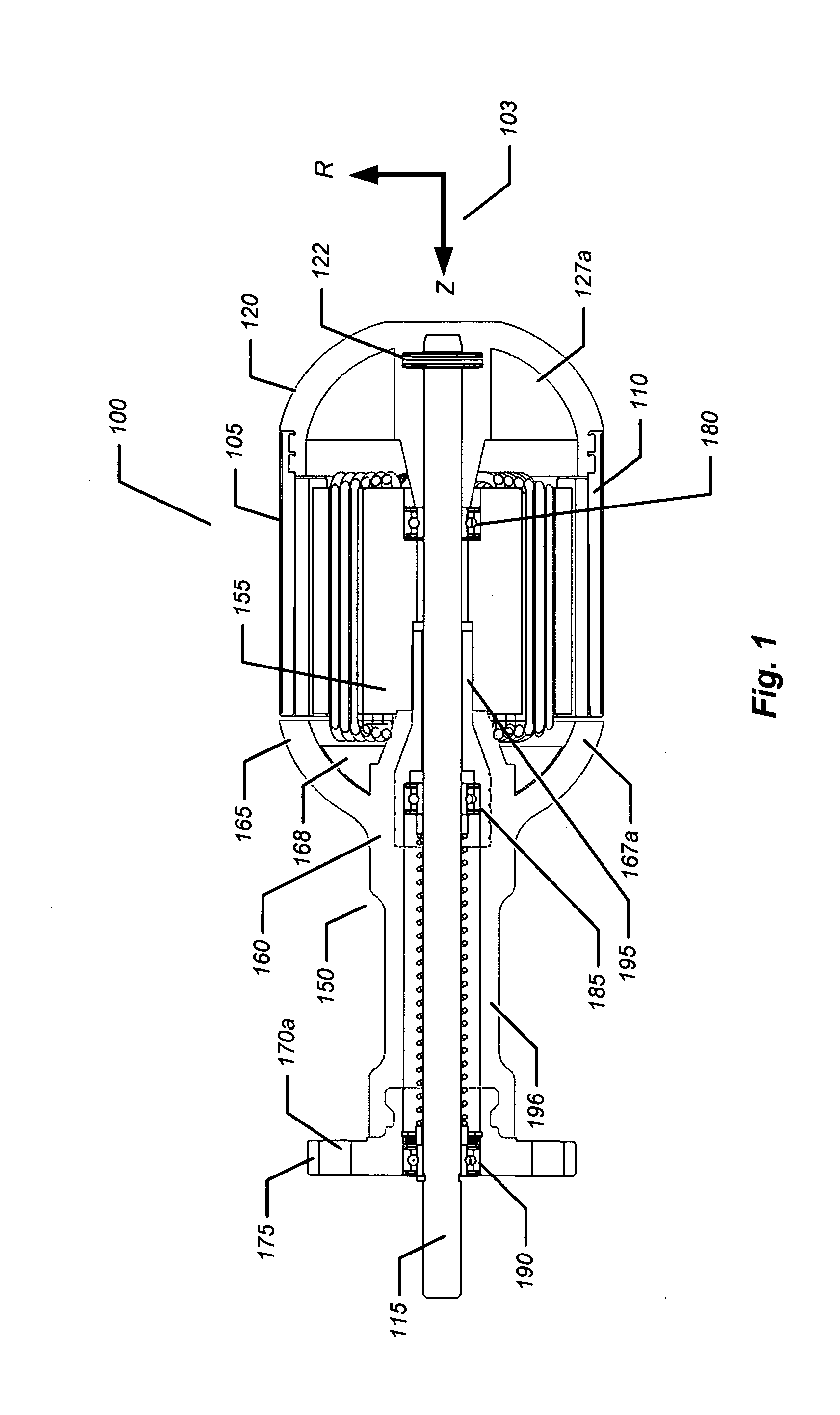
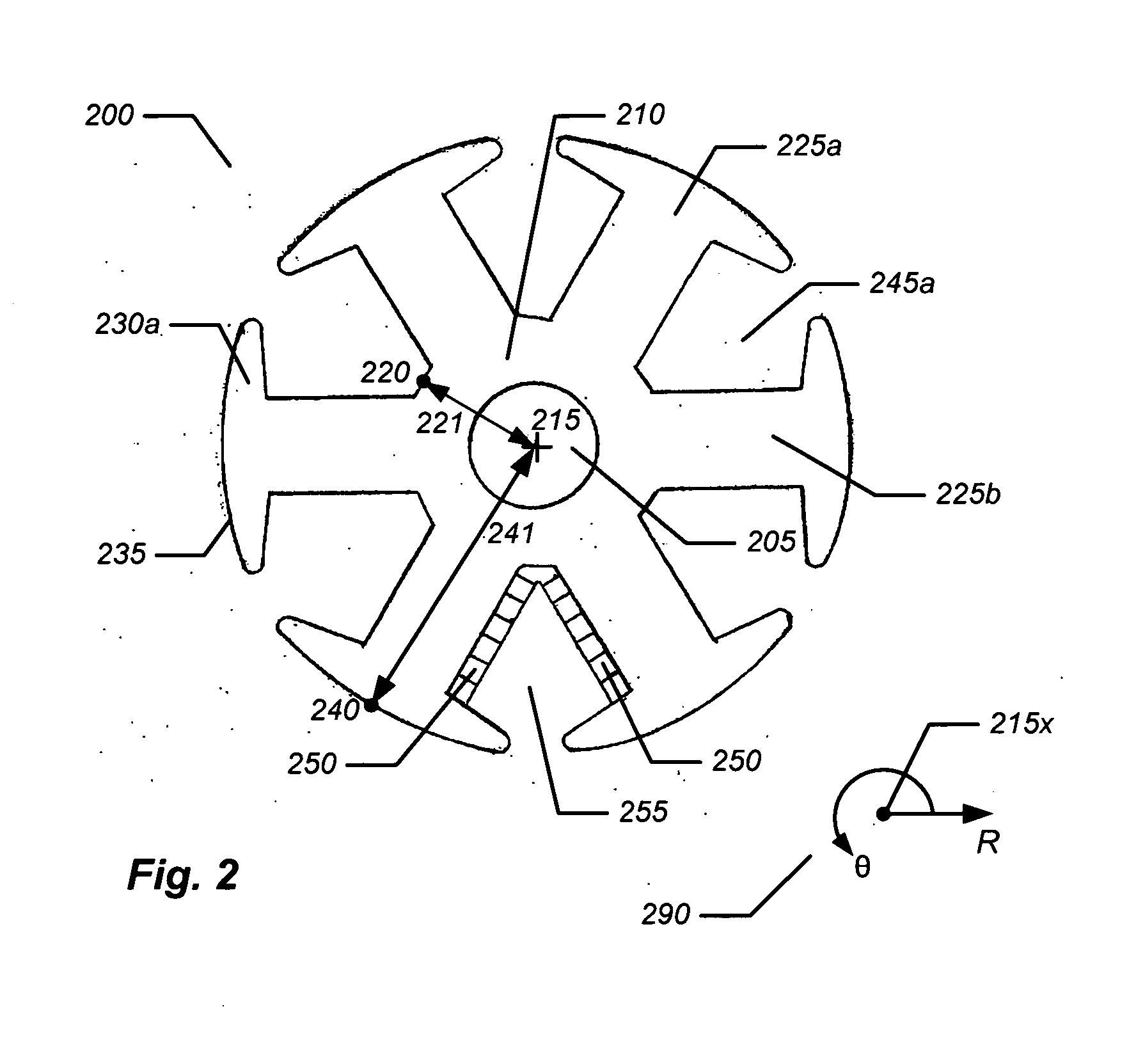
[0018]FIG. 1 depicts a first embodiment of the motor 100, shown in cross-section. To orient the figures, a cylindrical coordinate system (R, θ, Z) is used. The cross-section is in a plane parallel to the Z-axis. As shown by the inset 103 in FIG. 1, the Z-axis points along the axis of the shaft 115 of the motor 100, toward the end where the shaft 115 would engage the load when the motor 100 is operational. The R-direction is radially outward from the axis of the shaft 115. θ (see FIG. 2) is an angle about the Z-axis, in a plane perpendicular to the Z-axis.

[0019]The motor 100 includes a rotor assembly 105 and a stator assembly 150. The rotor assembly 105 is made up of a rotor cylinder 110 and the power delivery...


PUM


Abstract

The present invention is a brushless electric motor that can be used in high performance applications, such as model airplanes. The rotor assembly, which includes the rotor shaft, encloses a winding core, which is part of a fixed stator assembly. Conducting wire in the armature portion of the stator assembly is wrapped around a set of spokes, extending radially from an inner hub. The spokes are formed from a stack of flat metal laminations, the laminations oriented perpendicular to the rotation axis. The spokes are wrapped with a single layer of copper wire, which is connected to the energy source when the motor is operational. These spokes are long relative to the diameter of the inner hub, leaving V-shaped slots through the winding core. Openings in both end bells allow air to freely flow into the core, cooling the single layer of conducting wire. Using a wedge to force the wire against the spokes during varnishing results in close contact between the wire and the conducting material in the winding core. When the motor is operational, this contact causes the winding core to act as a heat sink, allowing a relatively heavy motor to sustain high power without damage.

Description

CROSS-REFERENCES TO RELATED APPLICATIONS[0001]This application claims the benefit of U.S. Provisional Application No. 61 / 130,912, filed Jun. 4, 2008, having inventor Leslie Hoffman and entitled “Brushless Motor Apparatus,” and hereby incorporated by reference.FIELD OF THE INVENTION[0002]The present invention relates to electric motors. More specifically, the invention relates electronically commutated brushless motors.BACKGROUND OF THE INVENTION[0003]Brushless DC motors are widely used in hobby applications such as model aviation. The advent of lithium secondary batteries and low “on” resistance power integrated circuits have permitted rapid advances in model aviation. The high power to weight ratios now available with electrically commutated motors powered by lithium batteries have permitted sustained flights of model helicopters and high speed ducted fan powered model jets. Traditional brushless motor designs for model aviation are derived from the CD / DVD-ROM drive industries. Des...

Claims


Application Information

Patent Timeline
Patent Type & Authority Applications(United States)
IPC IPC(8): H02K9/02
CPCH02K9/06H02K21/222H02K9/22H02K9/227
Inventor HOFFMAN, LESLIE
Owner HOFFMAN LESLIE
Why Eureka
Try Eureka