Illuminating device, backlight device, liquid crystal display device, method for controlling illuminating device and method for controlling liquid crystal display device

a technology of liquid crystal display and backlight, which is applied in the direction of instruments, light sources, electroluminescent light sources, etc., can solve the problems of inability to improve the correction accuracy and uneven characteristics of light emitting elements, and achieve the effect of improving the correction accuracy and accurately correcting

Inactive Publication Date: 2009-12-10
SHARP KK
View PDF12 Cites 41 Cited by
  • Summary
  • Abstract
  • Description
  • Claims
  • Application Information

AI Technical Summary

Benefits of technology

[0014]In the present illuminating device, it is preferable that each of the light source module includes a temperature sensor and the control is performed based on the detected temperature by the sensor. The light emitting element changes its characteristic depending on its temperature. The light emitting quantity of each light source module is measured at the same time as the temperature of each light source is measured, and thereby a change quantity of light emitting quantity of light emitting element by such as secular variation in each light source module can be calculated. By controlling the driver circuit of each light source module based on the calculated change quantity of light emitting quantity, a light

Problems solved by technology

However, light emitting elements are uneven in characteristic.
However, when the light emitting quantity is detected or corrected in the condition that the each illuminat

Method used


Image

  • Illuminating device, backlight device, liquid crystal display device, method for controlling illuminating device and method for controlling liquid crystal display device
  • Illuminating device, backlight device, liquid crystal display device, method for controlling illuminating device and method for controlling liquid crystal display device
  • Illuminating device, backlight device, liquid crystal display device, method for controlling illuminating device and method for controlling liquid crystal display device

Examples


Embodiment Construction

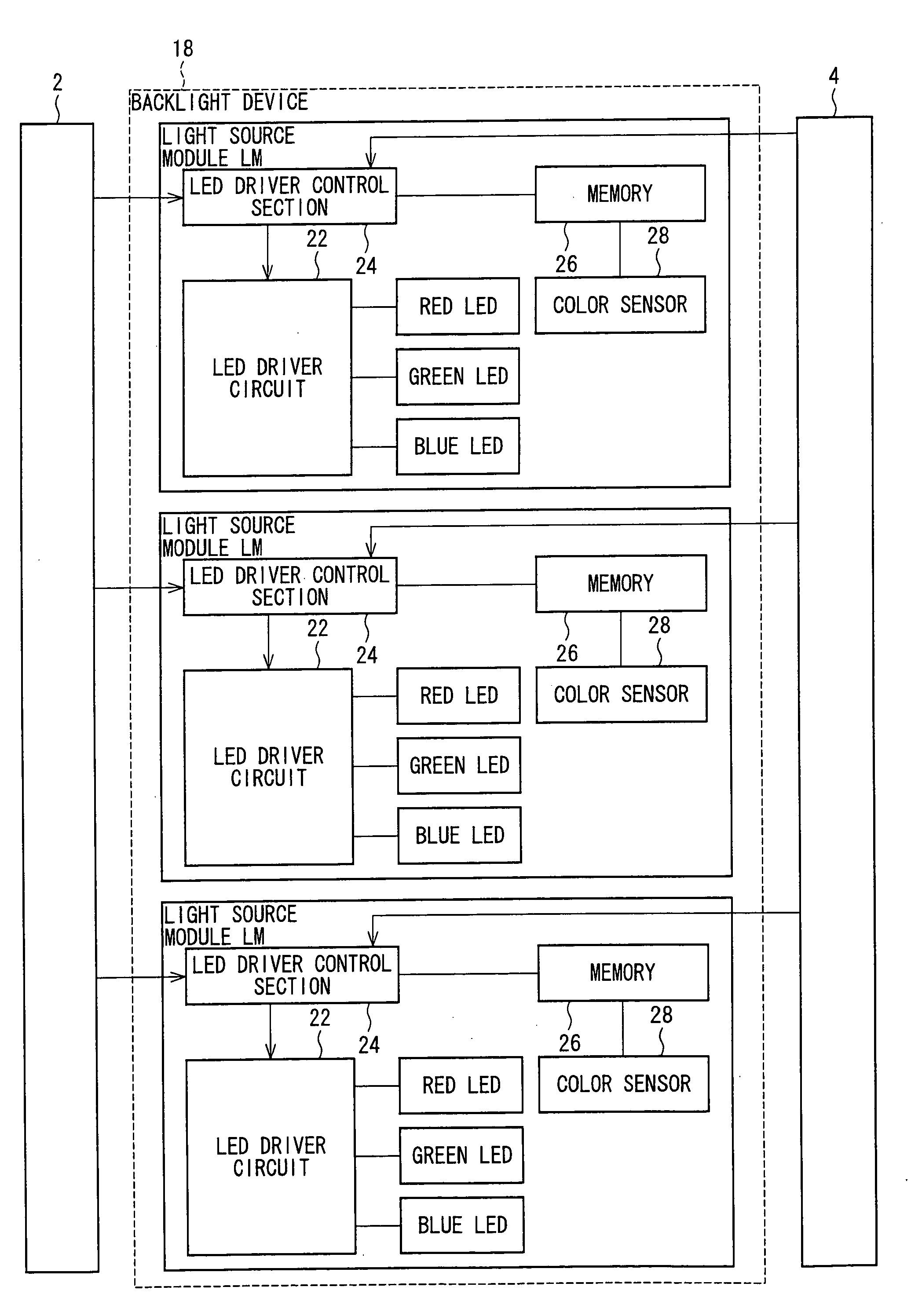
[0050]Embodiments of the present invention are described below with reference to FIGS. 1 to 8. As shown in FIG. 4, an embodiment of a liquid crystal display device 10 is provided with a liquid crystal panel 9, a liquid crystal panel driver circuit 3, a controller 2, a present backlight device 18, a light element such as diffusion panel (not illustrated), and a power supply control section 4. The controller 2 controls the liquid crystal panel driver circuit 3 and the backlight device 18 based on inputted image data. Under the control by the controller 2, liquid crystal panel driver circuit 3 drives the liquid crystal panel 9. The backlight device 18 emits light following the control by the controller 2. The light emitted from the backlight device 18 is supplied to the liquid crystal panel 9 through such as a diffusion panel (not illustrated). Moreover, the power supply control section 4 controls the power supply system of the liquid crystal display device 10 according to whether the ...


PUM


Abstract

An illuminating device is provided with a plurality of light source modules (LM) each of which has a light emitting element and a driver circuit for driving the light emitting element, and the illuminating device controls the driver circuit of each light source module individually. All the light. source modules are grouped by having a plurality of light source modules arranged at intervals (d) as one group. A step of lighting light emitting bodies of the light source modules in the same group (for instance, LM (1, 1)·LM (1, 9)) simultaneously under predetermined conditions is performed in turn for all the groups. Based on the obtained light emitting quantity of the light emitting element of each light source module (LM), the driver circuit of the light source module is controlled. Thus, in a backlight device provided with a plurality of illuminating areas, the light emitting quantity in each illuminating area can be accurately corrected in a short time.

Description

TECHNICAL FIELD[0001]The present invention relates to an illuminating device used for a display device such as a liquid crystal display device.BACKGROUND ART[0002]A conventional backlight device for a non-illuminating type display device such as a liquid crystal display device emits light with fixed brightness. The brightness of the backlight is set so that a display screen can attain maximum brightness. However, when the brightness of the backlight is fixed regardless of the displayed images, unnecessary power is consumed because the power does not contribute to display black or dark images. Moreover, some light of the backlight leaks when displaying black, and the leakage of light causes decrease of the contrast.[0003]As is disclosed in Patent Documents 1 to 3, a display device (backlight) provided with a plurality of illuminating areas is proposed. The display device controls the brightness of each illuminating area depending on inputted image signals.[0004][Patent Document 1] Ja...

Claims


Application Information

Patent Timeline
IPC IPC(8): G02F1/1335H05B37/02
CPCG02F1/133603G02F2001/133601G09G3/3426H05B33/0869G09G2320/041G09G2360/148G09G2320/0233H05B45/22H05B45/28G02F1/133601
Inventor AKE, YASUNORIUEHARA, KAZUHIROYAMANE, YASUKUNI
Owner SHARP KK
Why Eureka
Try Eureka