

Undulation Inspection Device, Undulation Inspecting Method, Control Program for Undulation Inspection Device, and Recording Medium
- Summary
- Abstract
- Description
- Claims
- Application Information
AI Technical Summary
Benefits of technology
Problems solved by technology
Method used
Image

Examples
Embodiment Construction
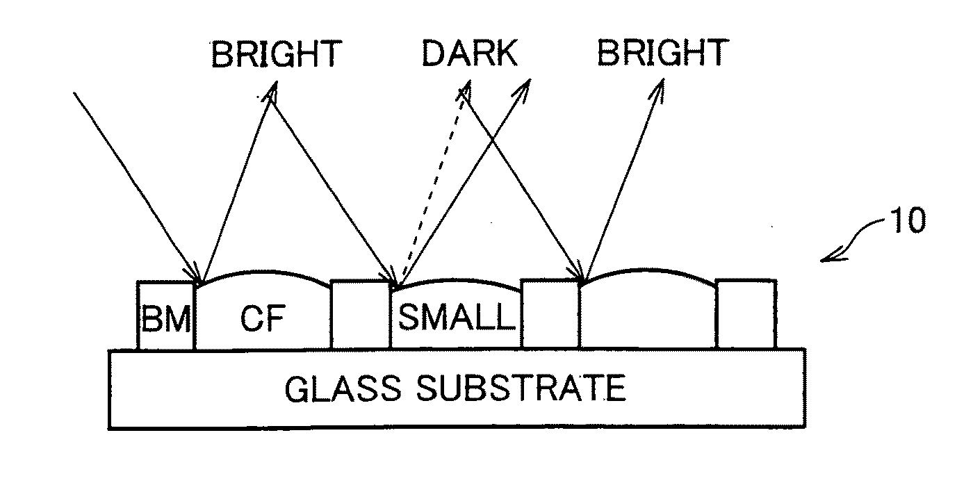
[0072]An undulation inspection device of the present invention can inspect any object, as an inspection target, as long as the object has a subtle undulation on a surface. Examples of the inspection target are a color filter substrate (particularly, a color filter substrate that is formed by using an ink jet method), a semiconductor wafer on which an exposure resist is formed, and a TFT substrate. The following explains, as one embodiment of the undulation inspection device of the present invention, a case where a color filter substrate is an inspection target.
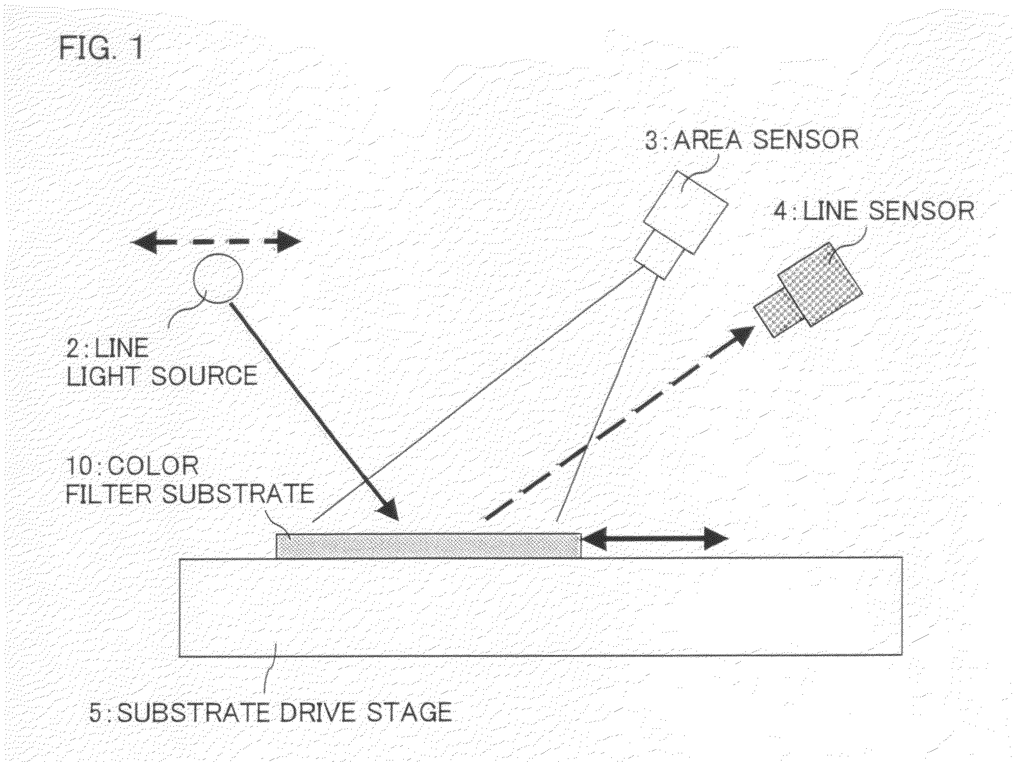
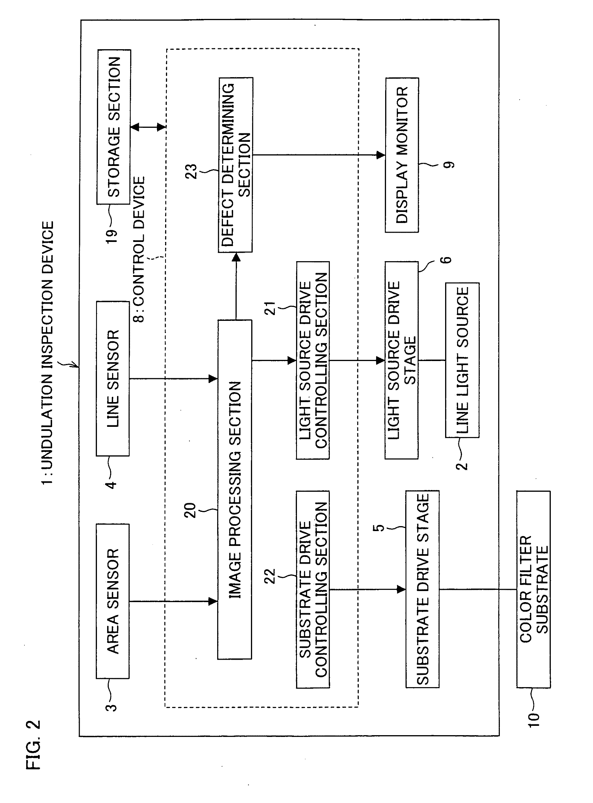
[0073]FIG. 1 is a diagram schematically illustrating a substantial part of the undulation inspection device of the present invention. FIG. 2 is a block diagram of the undulation inspection device. As shown in FIGS. 1 and 2, an undulation inspection device 1 includes a substrate drive stage 5, a line light source 2, an area sensor 3, a line sensor 4, a light source drive stage 6, a control device 8, a storage section 19, and a ...
PUM
 Abstract
Description
Claims
Application Information