Optical storage medium and optical information apparatus

Inactive Publication Date: 2009-12-10
PANASONIC CORP
View PDF5 Cites 7 Cited by
  • Summary
  • Abstract
  • Description
  • Claims
  • Application Information

AI Technical Summary

Benefits of technology

[0012]According to the above arrangements, even if the first beam for information recording/reproduction, and the second beam for servo control are emitted from the different light sources, the position for focusing control and the position for tracking control can be corrected to their respective intended positions based on the information obtained from the reference interference pattern used as the reference for correcting the relative positional relation between the first beam and the second

Problems solved by technology

As disclosed in the publication, however, in the case where the beam for servo control, and the beam for information recording/reproduction are different, there is no guarantee that a

Method used


Image

  • Optical storage medium and optical information apparatus
  • Optical storage medium and optical information apparatus
  • Optical storage medium and optical information apparatus

Examples


first embodiment

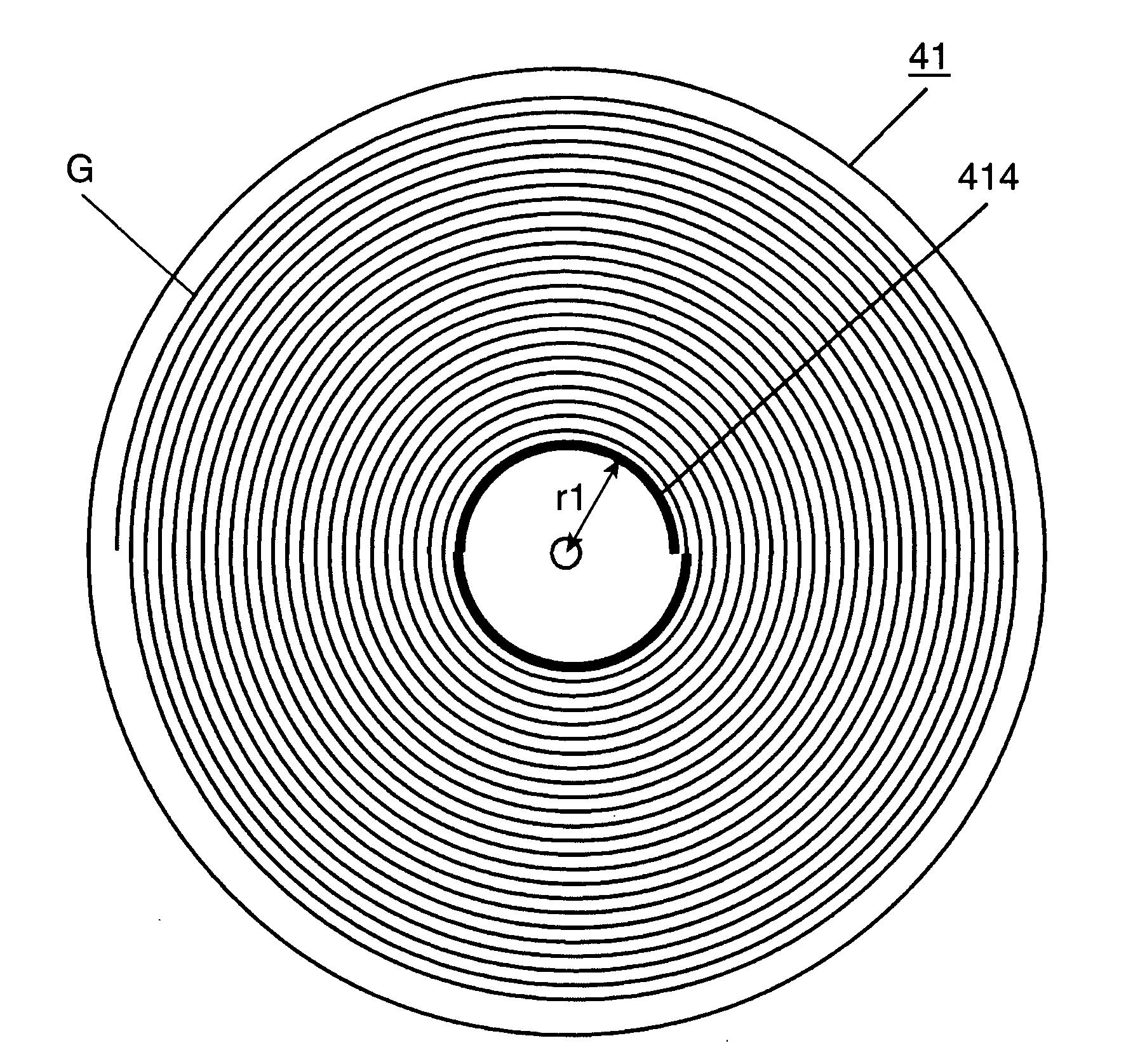
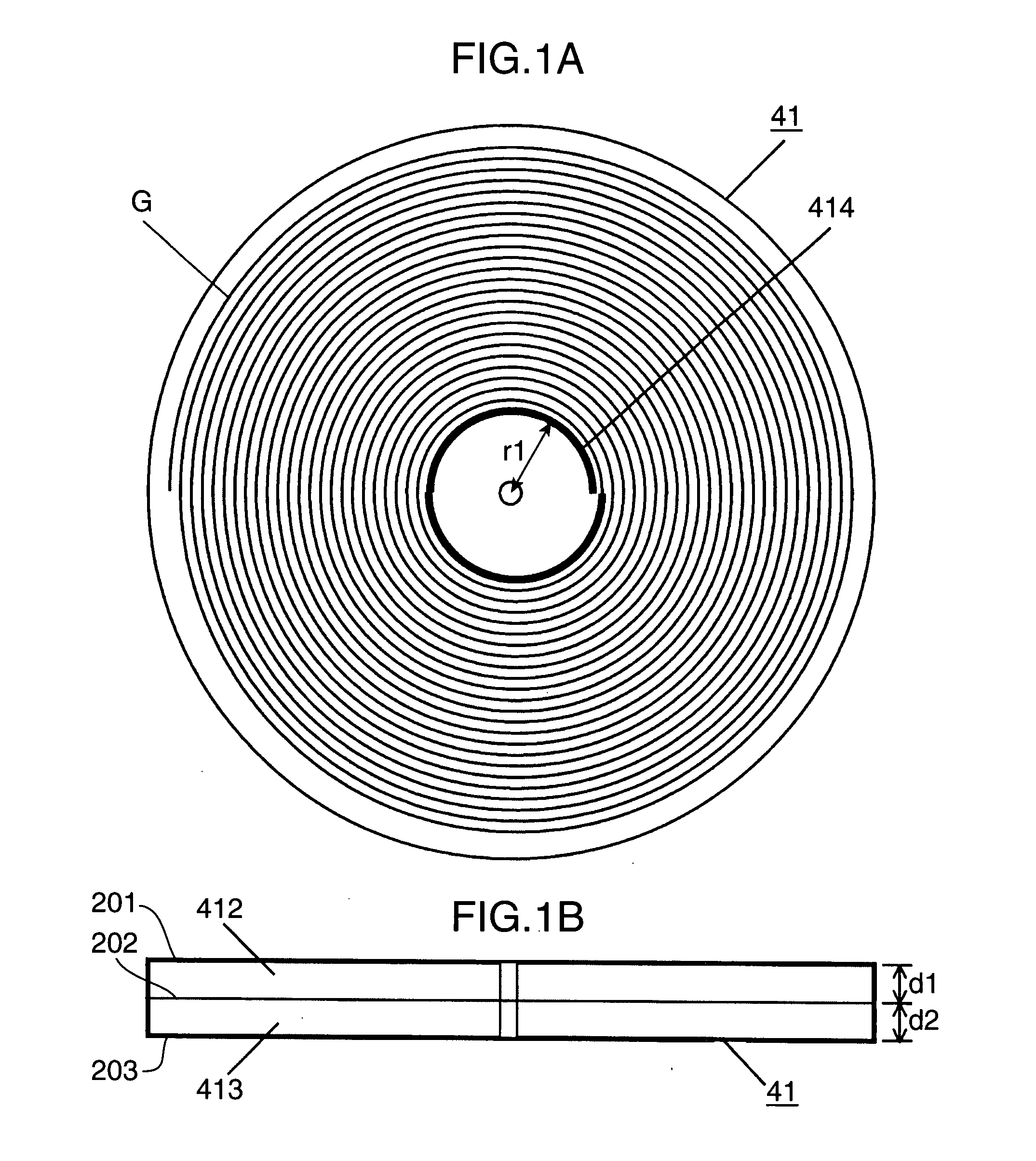
[0023]FIG. 1A is a diagram schematically showing an arrangement of an optical storage medium 41. FIG. 1B is a diagram schematically showing a cross-section of the optical storage medium 41. The optical storage medium 41 includes an information storage layer 412 made of a photosensitive resin material, and a base member 413. The photosensitive resin material is a photopolymer utilizing a light curing monomer resin. Various resin materials such as radical monomers and cationic monomers are usable.

[0024]The information storage layer 412 has a physical thickness “d1” of 0.6 mm, and the base member 413 has a physical thickness “d2” of 0.6 mm. The optical storage medium 41 has a disk-shaped outer contour, with a diameter of 120 mm. The optical storage medium 41 is spirally formed with a guide groove “G” capable of detecting a tracking error signal. The guide groove “G” serves as tracks in tracking control. Each track has a pitch of about 1 μm. The guide groove “G” is formed in the base me...

second embodiment

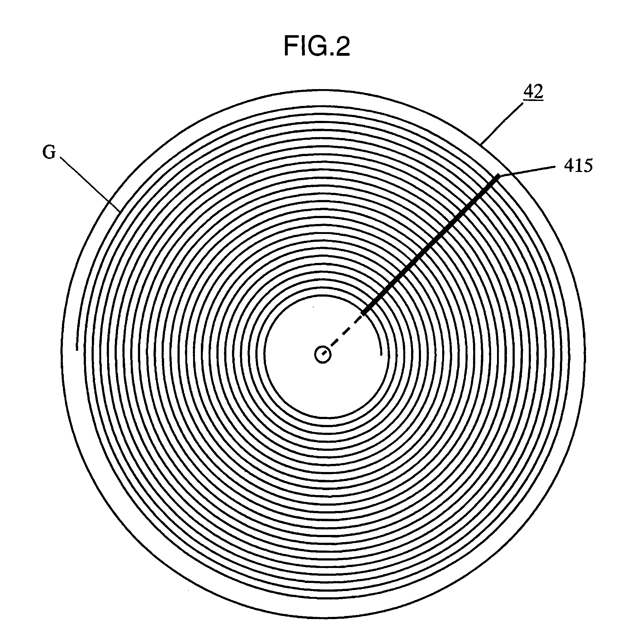
[0036]FIG. 2 is a diagram schematically showing an arrangement of an optical storage medium 42 in another embodiment of the invention. Although not illustrated, the basic arrangement of the optical storage medium 42 in the second embodiment is substantially the same as that of the optical storage medium 41 shown in the first embodiment.

[0037]The optical storage medium 42 is different from the optical storage medium 41 in the position where a reference interference pattern is formed on the optical storage medium. Whereas the reference interference patterns 414 are formed at the positions away from the center of the optical storage medium 41 by the radius “r1”, the reference interference patterns 415 each extends radially from the center of the optical storage medium 42. Specifically, in the second embodiment, the reference interference patterns 415 are formed linearly and radially outwardly from the center of the optical storage medium 42. Generally, the thickness, the warp, or the l...

third embodiment

[0047]FIG. 4 is a diagram schematically showing an arrangement of an example of an optical information apparatus embodying the invention. The optical information apparatus includes a first light source 701 and a second light source 719. The first light source 701 has a solid laser using Nd:YAG crystal, and a nonlinear device composed of lithium niobate. The first light source 701 is operated in such a manner that incidence of a beam of a wavelength of 1,064 nm emitted from the solid laser onto the lithium niobate crystal with a waveguide channel for quasi phase matching generates a second harmonic wave, thereby obtaining a beam of a wavelength of 532 nm.

[0048]The first light source 701 emits a linear polarized divergent beam 801 of a wavelength λ1=532 nm, as a first beam. The beam 801 is collimated into collimated beams through a lens 702. After the collimation, the beam 801 is split into two beams 802 and 803 by a beam splitter 703. The beam 802 reflected on the beam splitter 703 i...


PUM


Abstract

Disclosed is an arrangement that enables to keep a relative positional relation between a beam for servo control and a beam for information recording/reproduction constant concerning focusing control and tracking control, even if the two beams are different from each other. An optical storage medium has a reflection surface for reflecting a first beam having a first wavelength, and reflecting a second beam having a second wavelength different from the first wavelength; and an information storage layer for recording information as an interference pattern by incidence of the first beam, or reproducing the information from a wave surface based on the interference pattern. The reflection surface is formed with plural marks or guide grooves usable in a tracking operation or a focusing operation by irradiation of the second beam. The information storage layer is partially formed, in advance, with a reference interference pattern which is reproduced when the first beam is irradiated, and which is used as a reference for correcting the relative positional relation between the first beam and the second beam.

Description

TECHNICAL FIELD[0001]The present invention relates to an optical storage medium for recording information using an interference pattern, and an optical information apparatus for recording, reproducing, or erasing information.BACKGROUND ART[0002]Advanced technical development has been made with times in the technical field of optical information. The amount of information to be recorded in various optical storage media such as a compact disk (CD), a digital versatile disk (DVD), and a Blu-ray disk has been increasing. A Blu-ray disk having two information recording layers for recording information, with a disk diameter of 12 cm, has a storage capacity as large as 50 gigabytes (GB).[0003]In recent years, development of volume holography has been active to realize optical recording of a larger capacity than the Blu-ray disk. Holographic recording is conducted by superimposing information light and reference light inside an optical storage medium and by writing an interference pattern g...

Claims


Application Information

Patent Timeline
IPC IPC(8): G11B7/00G11B7/24
CPCG11B7/0065G11B7/24044G11B7/09G11B7/00781
Inventor KADOWAKI, SHINICHIKASAZUMI, KENICHIYAMAMOTO, KAZUHISAMIZUSHIMA, TETSUROSUGITA, TOMOYA
Owner PANASONIC CORP
Why Eureka
Try Eureka