Molding apparatus

a technology of molding apparatus and cylinder head, which is applied in the direction of presses, magnetic bodies, manufacturing tools, etc., can solve the problems of inability to achieve improvement in magnetic properties and inability to obtain high orientation, and achieve the effect of high orientation

Inactive Publication Date: 2009-12-10
ULVAC INC
View PDF6 Cites 12 Cited by
  • Summary
  • Abstract
  • Description
  • Claims
  • Application Information

AI Technical Summary

Benefits of technology

[0017]As described hereinabove, according to the molding apparatus of this invention, there can be obtained an effect in that crystal fractures of the powder having more equal crystal orientational relationship in the magnetic field or in the electric field are arranged to get combined, thereby manufacturing a molded body of an extremely high orientation.

Problems solved by technology

However, at the time of compression molding by means of the pair of punches, high orientation cannot be obtained, and the improvement in the magnetic properties cannot be attained, due to the friction among the particles of the alloy raw meal powder and due to the friction between the alloy raw meal powder and the wall surface of the mold set in position in the punch.

Method used


Image

  • Molding apparatus
  • Molding apparatus
  • Molding apparatus

Examples


Embodiment Construction

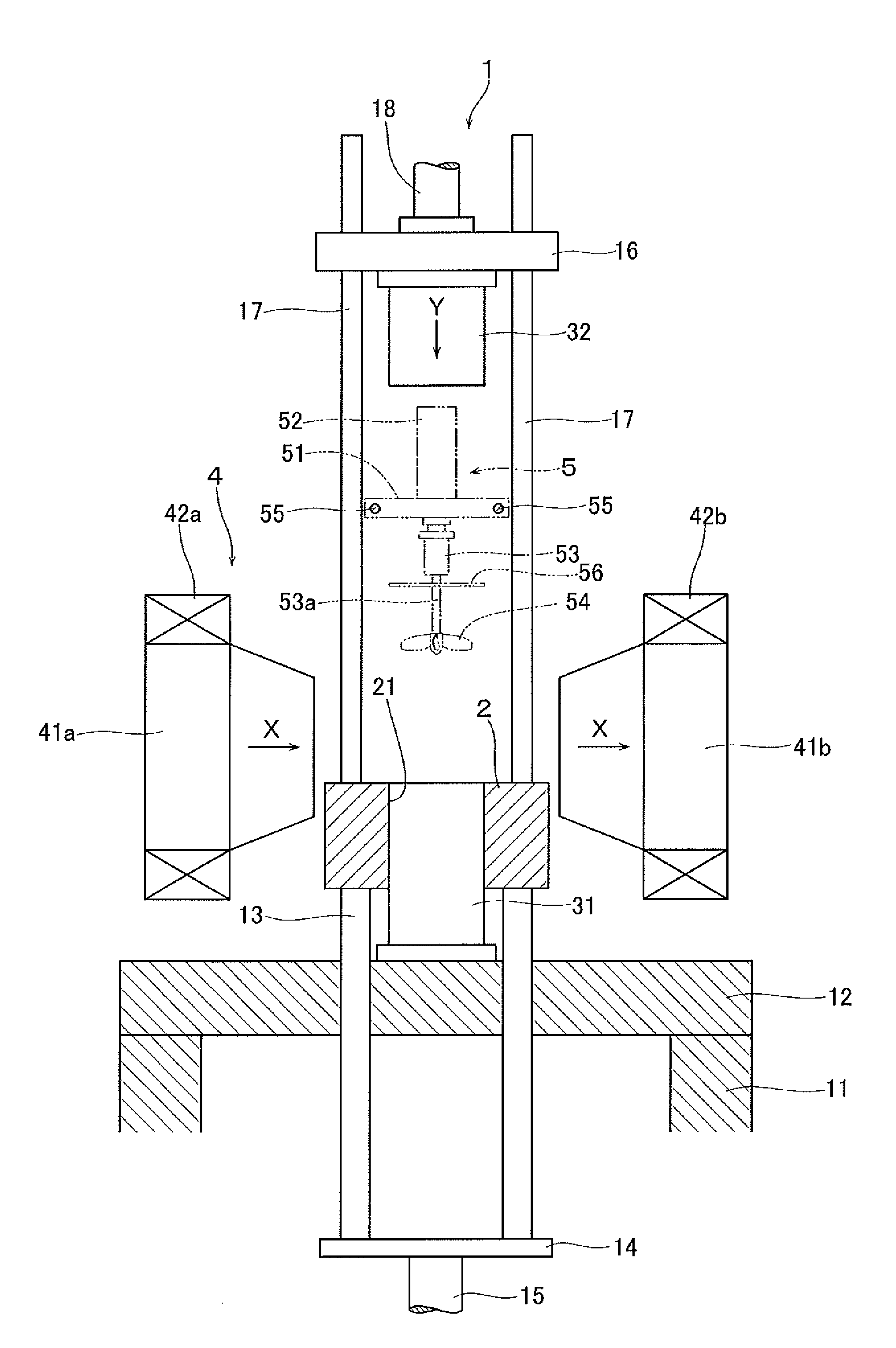
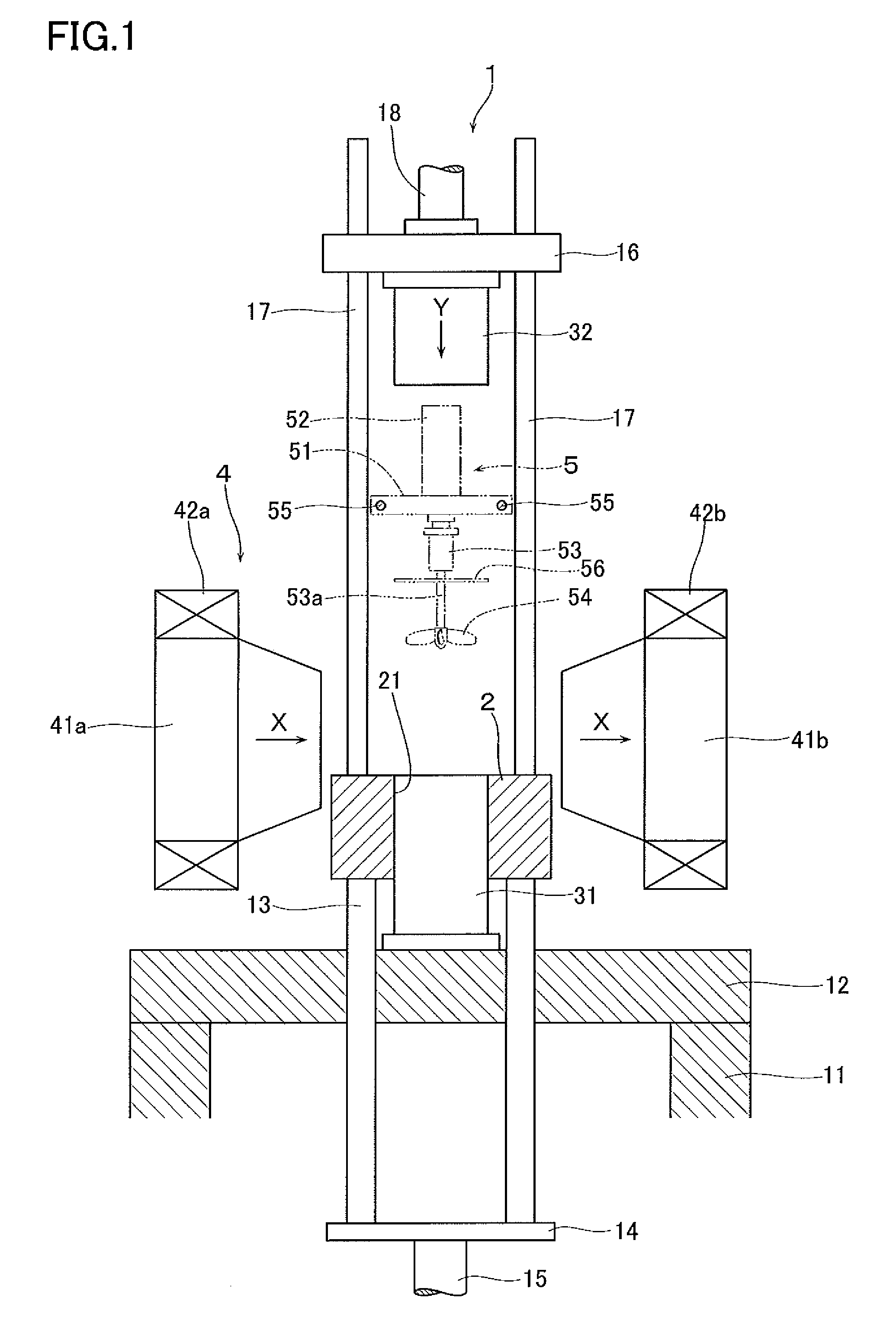
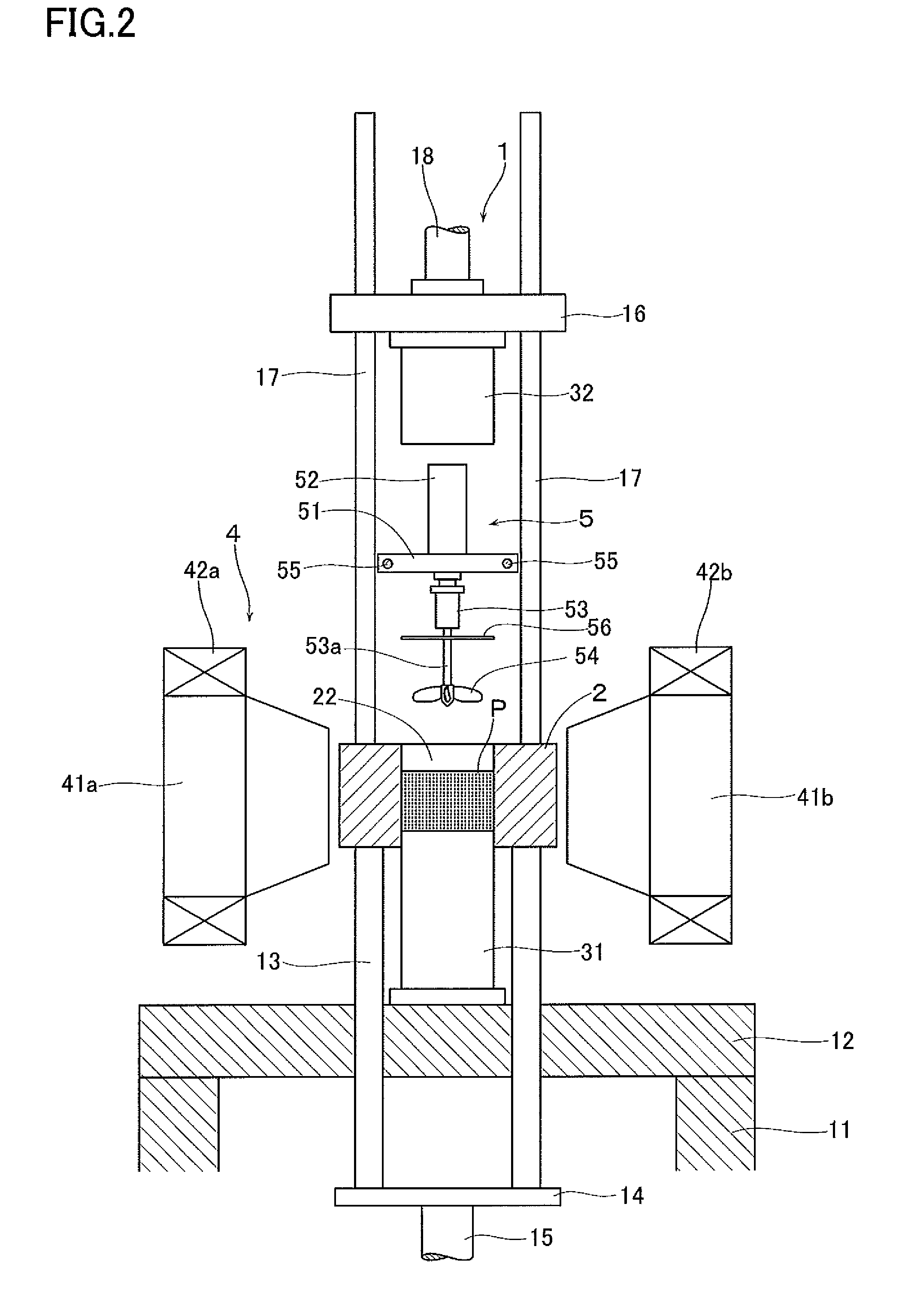
[0018]With reference to FIGS. 1 through 5, reference numeral 1 denotes a molding apparatus according to this invention. The molding apparatus 1 is suitable for manufacturing rare earth permanent magnet, in particular, Nd—Fe—B sintered magnet (inclusive of oriented body and molded body). The molding apparatus 1 is a compression molding apparatus of a uniaxial pressurizing type in which the direction of pressurizing (pressing direction) is vertical to the direction of magnetic orientation, and has a base plate 12 which is supported by leg pieces 11. Above the base plate 12 there is disposed a die 2. The die 2 is supported by a plurality of supporting columns 13 which penetrate through the base plate 12. The other end of each of the supporting columns 13 is connected to a connecting plate 14 disposed below the base plate 12. The connecting plate 14 is connected to a driving means, e.g., a cylinder rod 15 of a hydraulic cylinder of a known construction. According to this configuration, ...


PUM

PropertyMeasurementUnit
thickaaaaaaaaaa
particle sizeaaaaaaaaaa
timeaaaaaaaaaa

Abstract

By arranging such that the crystal fractures of alloy raw meal powder having crystal orientational relationship with one another get combined in the magnetic field, there is provided a molding apparatus which is capable of molding a molded body having an extremely high orientation. The molding apparatus of this invention has: a cavity for filling thereinto a powder that is polarized in magnetic field or electric field; means for generating magnetic field or electric field capable of charging the powder filled in the cavity with the magnetic field or electric field; an agitating means for agitating the powder in a state of being charged with the magnetic field or the electric field, thereby orienting the powder; and a pressurizing means for applying a compression force in the magnetic field or electric field to the agitated and oriented product.

Description

[0001]This application is a national phase entry under 35 U.S.C. §371 of PCT Patent Application No. PCT / JP2007 / 73480, filed on Dec. 5, 2007, which claims priority under 35 U.S.C. § 119 to Japanese Patent Application No. 2007-003401, filed Jan. 11, 2007, both of which are incorporated by reference.FIELD OF THE INVENTION[0002]The present invention relates to a molding apparatus for manufacturing a molded body by compression-molding a powder and relates, in particular, to a molding apparatus to be used in manufacturing a rare-earth permanent magnet such as a Nd—Fe—B system permanent magnet.BACKGROUND ART[0003]Rare-earth permanent magnets, particularly Nd—Fe—B sintered magnets (so-called neodymium magnet) are made of a combination of iron with elements of Nd and B that are low-priced and abundant as natural resources and also capable of stable supply, and can therefore be manufactured at a low cost and, at the same time, have high magnetic properties (maximum energy product is about 10 ...

Claims


Application Information

Patent Timeline
Patent Type & Authority Applications(United States)
IPC IPC(8): B22F3/087B22F3/00
CPCB22F3/004B22F3/03B22F3/087B22F2999/00B30B11/008H01F41/0266H01F41/0273B22F2202/05B22F2202/06B22F2202/17B22F3/02H01F1/053H01F1/08H01F13/00
Inventor NAGATA, HIROSHISHINGAKI, YOSHINORI
Owner ULVAC INC
Why Eureka
Try Eureka