Platform screen door system

a platform and gate technology, applied in door/window fittings, railway tracks, wing suspension devices, etc., can solve the problems of passengers' litter, significant disruption of the network, and the basic platform arrangement, and achieve the effect of shortening the pitch

Inactive Publication Date: 2009-12-17
KNORR BREMSE RAIL SYST UK LTD
View PDF26 Cites 5 Cited by
  • Summary
  • Abstract
  • Description
  • Claims
  • Application Information

AI Technical Summary

Benefits of technology

[0012]The present disclosure relates to, among other things, a platform screen gate and door which can operate with a shorter pitch.

Problems solved by technology

However, the basic platform arrangement suffers from several well known problems, such as passengers falling under trains either deliberately or unintentionally and also litter from passengers falling onto the track.
Although incidents of people falling under trains are not common, they result in significant disruption to the network and are traumatic incidents for everyone present.
The problem of litter on the track has also increased in recent years and can represent a serious health and safety risk on underground or sub-surface systems where the litter will remain in tunnels until it is cleared up.
The full height system is usually adopted for newly built railway systems and is in practice essentially in air-conditioned systems, as otherwise the air conditioning system loses air to the rail tunnels, which is highly inefficient.
In such a system, the use of a full height screen door is precluded as the air throughput to the platform is insufficient to make conditions tolerable.
Additionally, many platforms on old systems are quite narrow and a full height screen would be claustrophobic.
However, it is often difficult to retrofit such a system to a platform as it is expensive to dig channels out of the platform and the channel itself will accumulate dirt.
Some solutions box in the mechanism but this approach suffers from the problem that the box stands proud of or extends from the platform forming a step which makes the system harder to use for wheelchair users.
A further problem is that on certain metro systems, the door pitch is quite short, which permits rapid embarkation and disembarkation of passengers.
The problem is particularly acute in that the loads that the sliding doors must resist must be reacted to over the length of the support and the known head structures are generally not able to provide this due to space constraints.

Method used


Image

  • Platform screen door system
  • Platform screen door system
  • Platform screen door system

Examples


Embodiment Construction

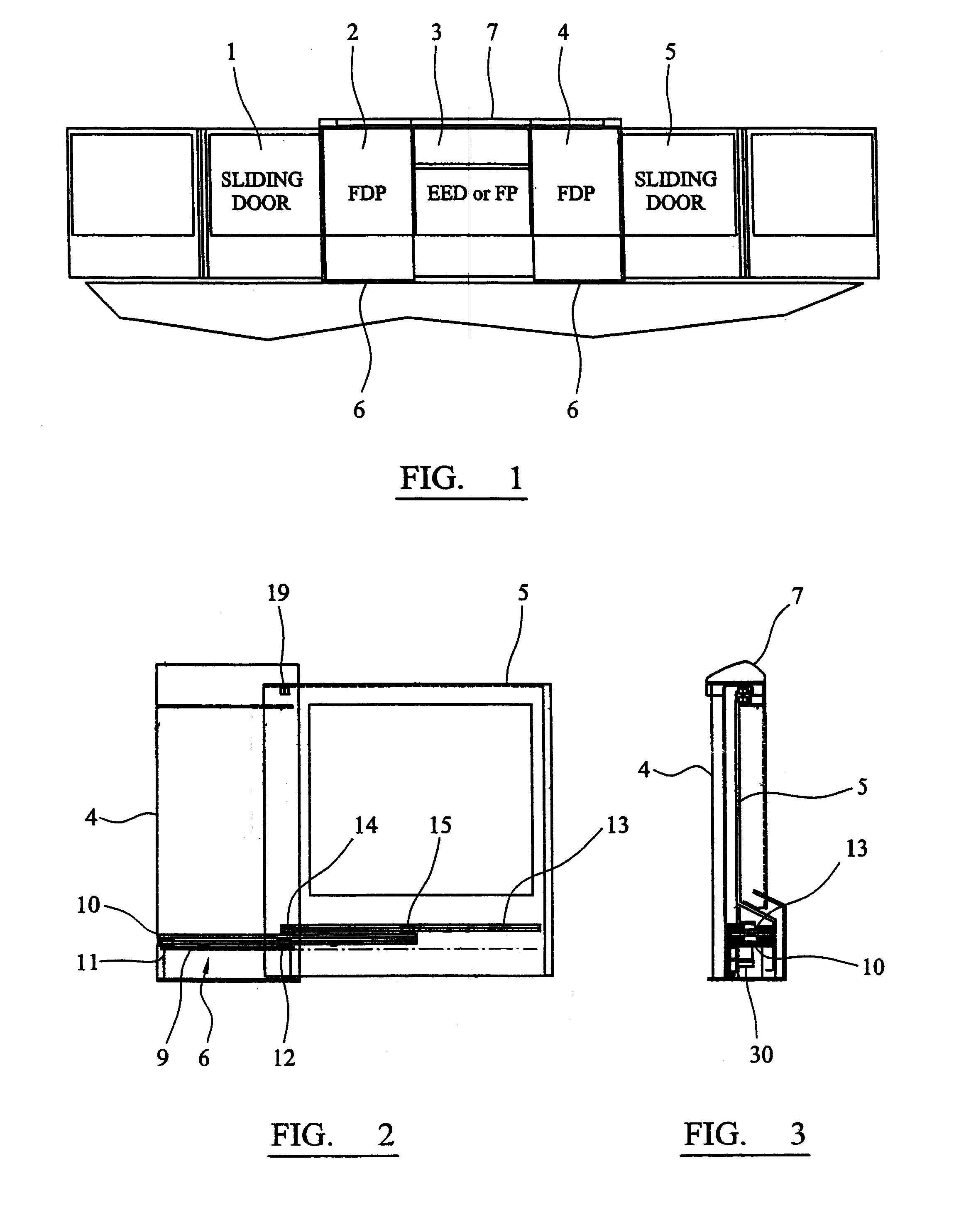
[0022]FIG. 1 shows a schematic of a platform screen door system with the sliding doors in the closed position on a railway platform. The system comprises a first sliding door 1 adjacent to a fixed driving panel 2, which fixed driving panel 2 is narrower than the sliding door 1. The fixed driving panel 2 is adjacent to a fixed panel 3 or the pivoting door, which in turn is adjacent to a further fixed driving panel 4, which is adjacent to a further sliding door 5. A guide 6 is provided at the lower edges of the fixed driving panels 2 and 4. A head structure 7 is provided on the upper edge of the fixed driving panels 2 and 4 and the fixed panel 3.

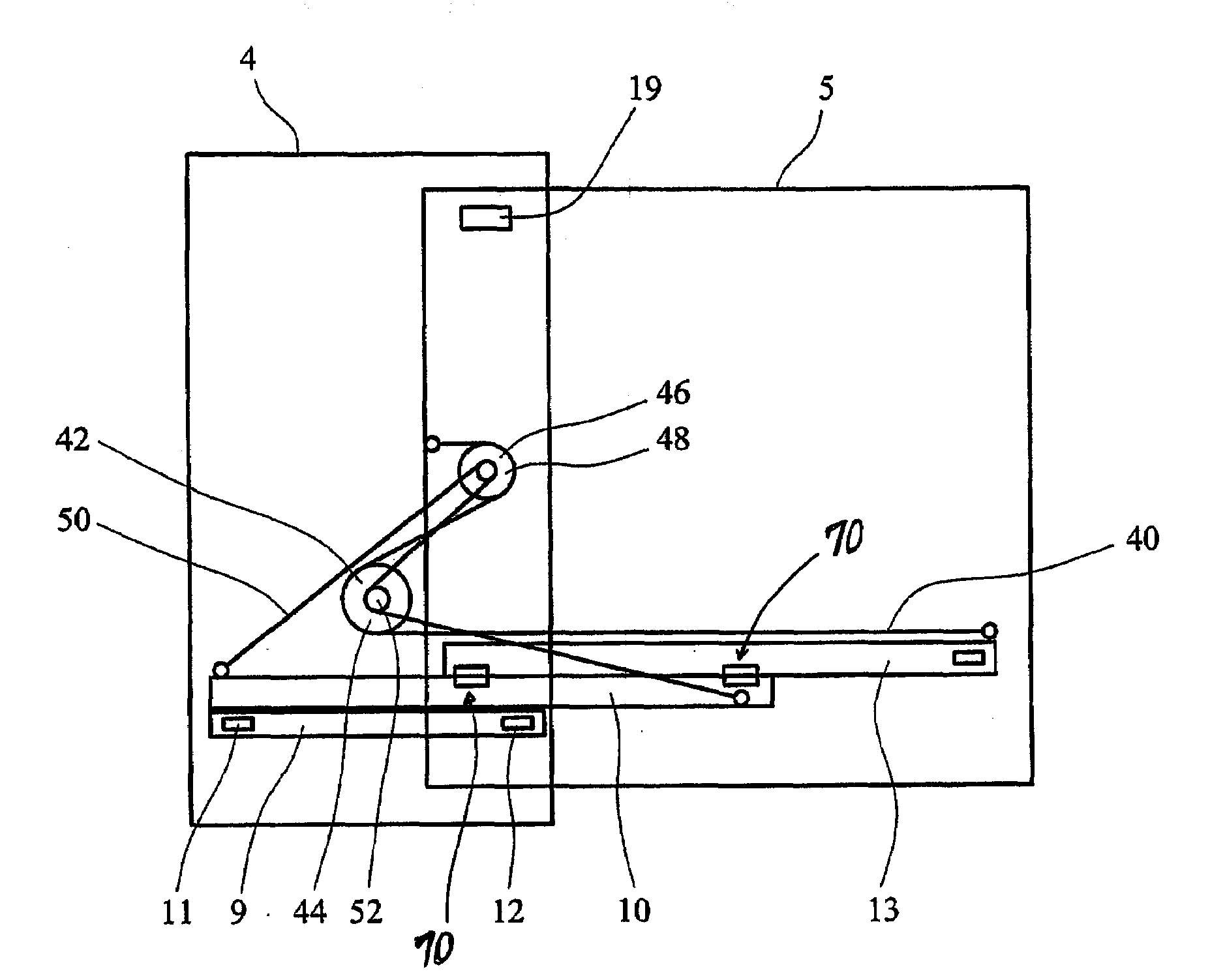
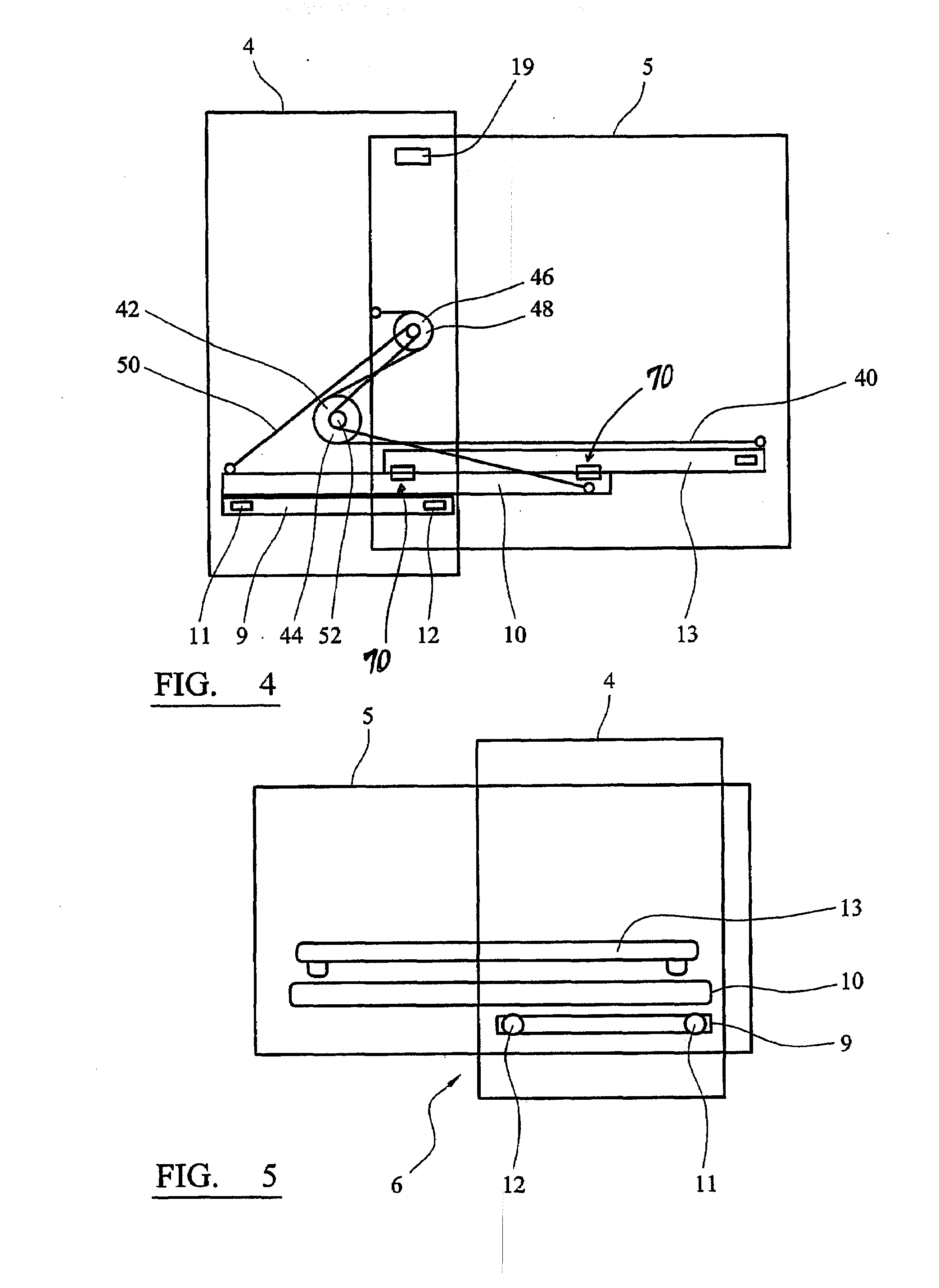
[0023]FIG. 2 shows the fixed driving panel 4 and the sliding door 5 in the closed position with the guide 6. The guide 6 comprises a fixed guide 9 comprising two rollers 11, 12 mounted on the frame of the fixed driving panel 4. The guide 6 further comprises a moving door guide 13 and a moving intermediate door guide 10. The intermediate door g...


PUM


Abstract

A platform screen door system includes a fixed driving panel and at least one door leaf slidable relative to the fixed driving panel. Further included is a telescopic guide including a fixed guide mounted on the fixed driving panel, a moving guide mounted on the at least one door leaf, and a moving intermediate guide mounted on the fixed guide. Also included is a drive means for slidably moving the at least one door leaf from a closed position to an opened position wherein the at least one door leaf overlaps the fixed driving panel.

Description

CROSS-REFERENCE TO RELATED APPLICATIONS[0001]This application is a National Phase Application based upon and claiming the benefit of priority of PCT / GB2007 / 000921, filed on Mar. 15, 2007 which is hereby incorporated herein by reference.BACKGROUND AND SUMMARY[0002]The present disclosure relates to a platform screen door or gate and a mechanism for opening and closing the door or gate.[0003]The conventional railway station consisting of a raised platform adjacent to the track is essentially the same design as has been used since the beginning of the railway industry in the nineteenth century and is an effective solution to the problem of maximising passenger boarding speed.[0004]However, the basic platform arrangement suffers from several well known problems, such as passengers falling under trains either deliberately or unintentionally and also litter from passengers falling onto the track. Although incidents of people falling under trains are not common, they result in significant d...

Claims


Application Information

Patent Timeline
Patent Type & Authority Applications(United States)
IPC IPC(8): E05D15/06E05F15/14
CPCB61B1/02E05D15/0686E05F15/643E05Y2800/122E05Y2900/404E05Y2201/684
Inventor HEMMINGS, MARK
Owner KNORR BREMSE RAIL SYST UK LTD
Why Eureka
Try Eureka