Control apparatus for internal combustion engine and method for controlling the same

a control apparatus and internal combustion engine technology, applied in mechanical devices, electric control, machines/engines, etc., can solve problems such as corrosion and corrosion of the internal cooling uni

Inactive Publication Date: 2009-12-17
TOYOTA JIDOSHA KK
View PDF6 Cites 18 Cited by
  • Summary
  • Abstract
  • Description
  • Claims
  • Application Information

AI Technical Summary

Benefits of technology

[0006]The invention provides a control apparatus for an internal combustion engine that executes a control for supplying an intake air to a bypass passage, through which an intake air flow bypasses an intercooler, based on the pH of the condensed water obtained from the exhaust gas, thereby ensuring reliability of the intercooler, and a method for controlling the control apparatus.

Problems solved by technology

However, the technology described in JP-A-2005-146919 has a disadvantage that the intercooler may corrode if the condensed water, which is obtained from the exhaust gas and recirculated by the low-pressure EGR system, is supplied to the intercooler.
Such corrosion may occur if strongly acidic condensed water is supplied to the intercooler.

Method used


Image

  • Control apparatus for internal combustion engine and method for controlling the same
  • Control apparatus for internal combustion engine and method for controlling the same
  • Control apparatus for internal combustion engine and method for controlling the same

Examples


first embodiment

of the Invention

[0021]First, a first embodiment of the invention will be described.

[0022]Structure of Apparatus

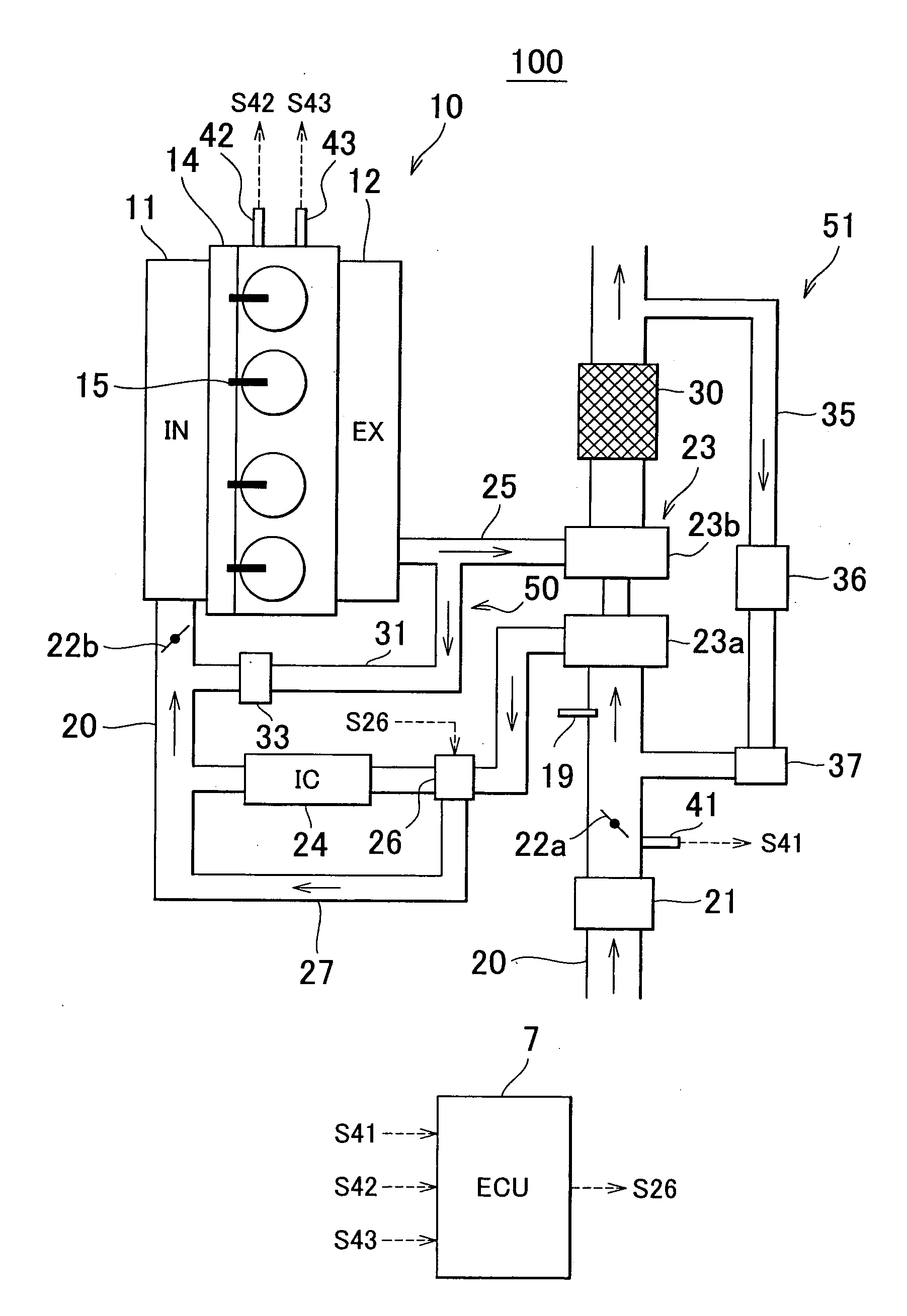
[0023]FIG. 1 is a block diagram schematically showing the structure of a control apparatus 100 for an internal combustion engine according to the first embodiment of the invention. In FIG. 1, solid arrows indicate a flow of the intake air and a flow of the exhaust gas, and dashed arrows indicate control signals and detection signals.

[0024]The control apparatus 100 in FIG. 1 includes an internal combustion engine 10 that is an in-line four-cylinder diesel engine. Each cylinder of the internal combustion engine 10 is connected to an intake manifold 11 and an exhaust manifold 12. The internal combustion engine 10 has fuel injection valves 15 provided to the respective cylinders, and a common-rail 14 that supplies high-pressure fuel to the fuel injection valves 15. The high-pressure fuel is supplied to the common-rail 14 by a fuel pump (not shown). An engine speed sensor 42 det...

second embodiment

of the Invention

[0050]Next, a second embodiment of the invention will be described. The second embodiment of the invention differs from the first embodiment of the invention in that the pH of the exhaust gas condensed water is detected by a sensor instead of estimating the pH of the exhaust gas condensed water. More specifically, according to the second embodiment of the invention, the pH of the exhaust gas condensed water is detected by a sensor that is provided to the intake passage 20, at a position upstream of the position at which the intercooler 24 is provided and downstream of the position to which the exhaust gas is recirculated back by the low-pressure loop EGR unit 51. Then, the ECU 7 determines whether the pH of the exhaust gas condensed water is at a level at which the intercooler 24 will corrode, based on the detected pH. After that, the ECU 7 executes the bypass control similar to that according to the first embodiment of the invention.

[0051]FIG. 5 is a block diagram s...


PUM


Abstract

A control apparatus for an internal combustion engine includes an exhaust gas recirculation unit; an intercooler that is provided in the intake passage, at a position downstream of a position to which the exhaust gas is recirculated back; a bypass passage through which an intake air flow bypasses the intercooler. When it is determined that the pH of the condensed water obtained from the exhaust gas is at the level at which the intercooler corrodes in the state where the exhaust gas is recirculated back by the exhaust gas recirculation unit, the control apparatus executes a control for cutting off an intake air flow toward the intercooler to direct the intake air flow only to the bypass passage. Thus, it is possible to ensure reliability of the intercooler.

Description

BACKGROUND OF THE INVENTION[0001]1. Field of the Invention[0002]The invention relates to a control apparatus for an internal combustion engine, which includes an exhaust gas recirculation passage through which exhaust gas is recirculated back from an exhaust passage to an intake passage, and a method for controlling the same.[0003]2. Description of the Related Art[0004]There has been suggested an exhaust gas recirculation (EGR) system for an internal combustion engine, for example, a diesel engine. The exhaust gas recirculation system recirculates a portion of exhaust gas back from an exhaust passage to an intake passage to decrease the combustion temperature in the engine, thereby suppressing generation of NOx. For example, an EGR system that recirculates exhaust gas back to an intake system from an exhaust passage at a portion downstream of a catalyst (hereinafter, referred to as a “low-pressure loop EGR system”) has been suggested. Japanese Patent Application Publication No. 2005...

Claims


Application Information

Patent Timeline
Patent Type & Authority Applications(United States)
IPC IPC(8): F02D23/00F02B33/44F02M25/07
CPCF02B29/0418F02D41/0065F02D2200/0418F02M25/0701F02M25/0707Y02T10/47F02M25/0718F02M25/0727F02M25/0744F02M25/0755Y02T10/146F02M25/0709F02M26/46F02M26/05F02M26/06F02M26/50F02M26/15F02M26/23F02M26/38Y02T10/12Y02T10/40
Inventor YAMASHITA, AKIRAMATSUMOTO, ISAOMAGARIDA, NAOFUMIMURATA, HIROKIHAGA, HIROYUKISAODA, TAKENORI
Owner TOYOTA JIDOSHA KK
Why Eureka
Try Eureka