Method for exfoliating carbonization catalyst from graphene sheet, method for transferring graphene sheet from which carbonization catalyst is exfoliated to device, graphene sheet and device using the graphene sheet

a carbonization catalyst and graphene sheet technology, applied in the direction of physical/chemical process catalysts, metal/metal-oxide/metal-hydroxide catalysts, paper/cardboard containers, etc., can solve the problem of easy and achieve the effect of preventing the damage of graphene sheets and easy damag

Active Publication Date: 2009-12-17
SAMSUNG ELECTRONICS CO LTD
View PDF1 Cites 69 Cited by
  • Summary
  • Abstract
  • Description
  • Claims
  • Application Information

AI Technical Summary

Benefits of technology

[0012]In these techniques, graphene sheet may be easily damaged when exfoliating the graphene sheet from the carbonization catalyst after the graphene sheet is formed on the carbonization cat...

Problems solved by technology

In these techniques, graphene sheet may be easily damaged when exfoliating the graphene shee...

Method used


Image

  • Method for exfoliating carbonization catalyst from graphene sheet, method for transferring graphene sheet from which carbonization catalyst is exfoliated to device, graphene sheet and device using the graphene sheet
  • Method for exfoliating carbonization catalyst from graphene sheet, method for transferring graphene sheet from which carbonization catalyst is exfoliated to device, graphene sheet and device using the graphene sheet
  • Method for exfoliating carbonization catalyst from graphene sheet, method for transferring graphene sheet from which carbonization catalyst is exfoliated to device, graphene sheet and device using the graphene sheet

Examples


experiment 1

[0078][ Variation in composition of binder layer]

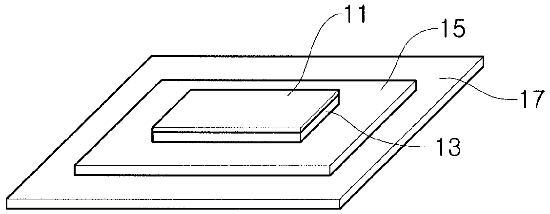
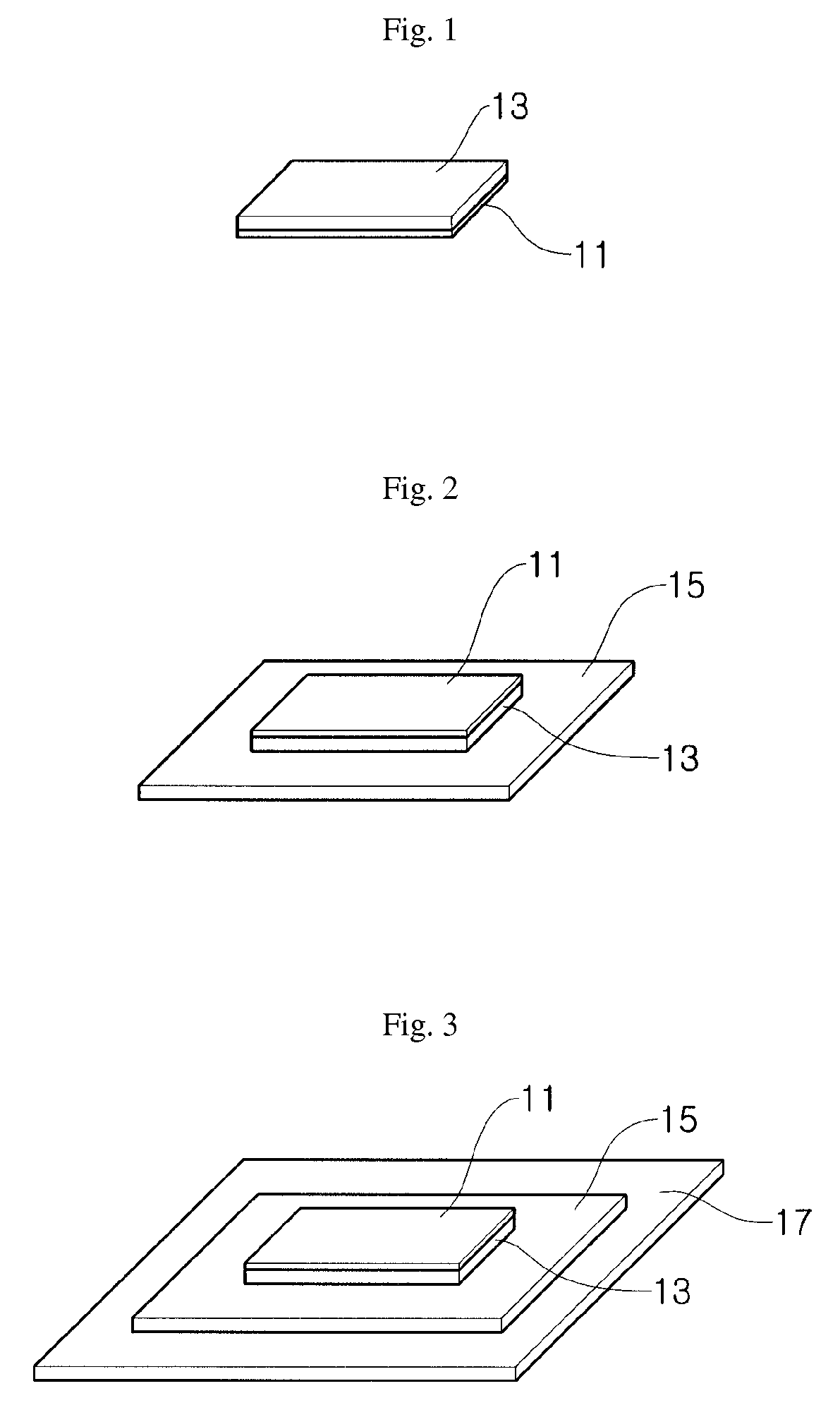
[0079]An about 0.5 mm-thick nickel plate with a size of about 1.2 cm×about 1.5 cm is prepared as a film-shaped carbonization catalyst. The nickel plate is positioned in a chamber, and heat-treated at about 1,000° C. for about 5 minutes using a halogen lamp heater while supplying acetylene gas into the chamber at a constant rate of about 200 sccm in order to form graphene on the film-shaped carbonization catalyst (i.e., on the nickel plate).

[0080]Subsequently, after removing the heater, the inside of the chamber is cooled rapidly. Graphene is thus grown to have a uniform spatial arrangement, and in this way an about 10-layered graphene sheet with a size of about 1.2 cm×about 1.5 cm is obtained.

[0081]On the about 10-layered graphene sheet, a coating layer of a binder material and a substrate (PET) are formed. The binder layers are formed to have a thickness of about 1 μm.

[0082]The coating of the binder material is carried out so that th...

experiment 2

[0095][Experiment 2: Inclusion of wetting agent]

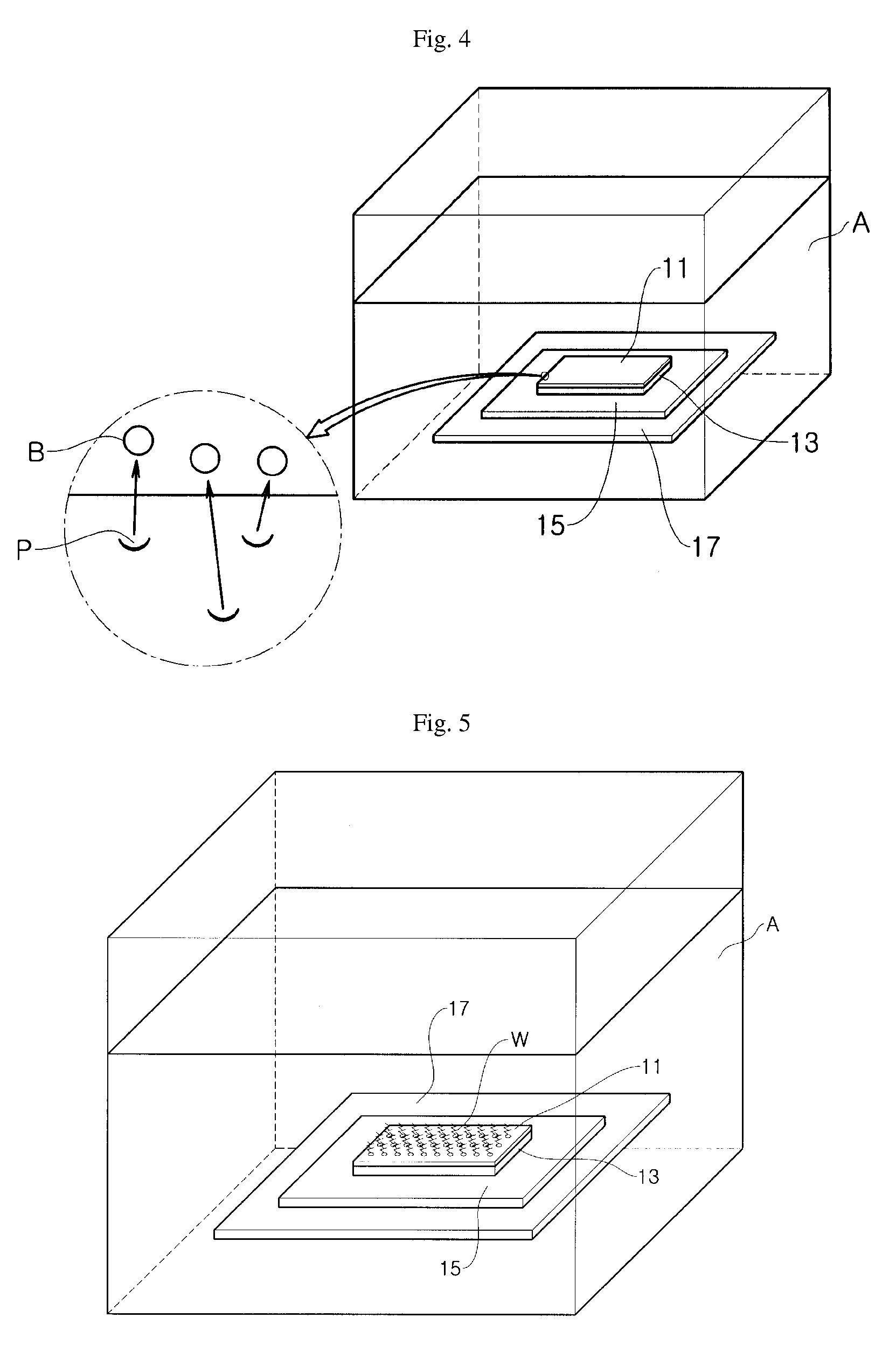
[0096]A graphene sheet is obtained in the same manner of Example 1 of Experiment 1, except for the differences in the wet etching step as noted hereinbelow.

[0097]As etchant solution for wet etching, about 55 ml, about 40 ml and about 25 ml of about 60 wt % nitric acid (HNO3) solutions are prepared. Potassium perfluorooctanesulfonate (wetting agent) of the following Chemical Formula 1 is added to nitric acid (sat.) to prepare about 15 ml, about 30 ml and about 55 ml of etching solutions having about 0.5 wt % wetting agent.

[0098]The volume of water is fixed at about 45 ml, and the volume of the wetting agent solution and the about 60 wt % nitric acid solution is controlled as in the following Table 3 in order to control the concentration of the wetting agent in the entire etchant solution.

TABLE 3Example 1Example 2Example 3Example 4Nitric acid solution (about 60 wt %)—About 25 mlAbout 40 mlAbout 55 mlWetting agent solution [about 0.5About...


PUM

PropertyMeasurementUnit
Fractionaaaaaaaaaa
Fractionaaaaaaaaaa
Thicknessaaaaaaaaaa

Abstract

A carbonization catalyst for forming graphene may be exfoliated from a graphene sheet by etching. A binder layer may be formed on the graphene sheet on which a carbonization catalyst is formed, to support and fix all or part of the graphene sheet. Further, the graphene sheet from which the carbonization catalyst is exfoliated may be transferred to a device. When exfoliating the carbonization catalyst from the graphene sheet, an acid may be used together with a wetting agent.

Description

[0001]This application claims priority to Korean Patent Application No. 10-2008-0055310, filed on Jun. 12, 2008, and all the benefits accruing therefrom under U.S.C. §119, the contents of which are hereby incorporated by reference in their entirety.BACKGROUND[0002]1. Field[0003]This disclosure relates to a method for exfoliating a carbonization catalyst from a graphene sheet grown on the carbonization catalyst, a method for transferring the graphene sheet to a device, a graphene sheet from which a carbonization catalyst is exfoliated and a device comprising the graphene sheet.[0004]2. Description of the Related Art[0005]Graphite may be formed of a stacked structure of two-dimensional planar sheets in which carbon atoms may be bonded in an extended fused array of hexagonal rings. A single sheet of the extended fused array of six-membered carbon rings may be referred to as graphene.[0006]Graphene sheet, as defined herein, may comprise one or more sheets of graphene. Graphene sheet may...

Claims


Application Information

Patent Timeline
IPC IPC(8): B32B37/02C01B31/04B44C1/22
CPCB01J23/02B01J23/16B01J23/42B01J23/52B01J23/70B32B43/006Y10T156/10B82Y40/00C01B31/0446C01B31/0484C01B2204/04C01P2004/24Y10S977/842B82Y30/00C01B32/184C01B32/194
Inventor SHIN, HYEON JINCHOI, JAEYOUNGYOON, SEONMI
Owner SAMSUNG ELECTRONICS CO LTD
Why Eureka
Try Eureka