Charged particle beam extraction method and apparatus used in conjunction with a charged particle cancer therapy system

a cancer therapy system and charge particle technology, applied in the field of solid tumor treatment, can solve the problems of large radiation being delivered outside of the tumor, x-rays not optimal for cancerous tissue treatment, and dangerous benign tumors in confined places

Active Publication Date: 2009-12-17
BALAKIN ANDREY VLADIMIROVICH +1
View PDF99 Cites 11 Cited by
  • Summary
  • Abstract
  • Description
  • Claims
  • Application Information

AI Technical Summary

Problems solved by technology

Benign tumors cause problems, because of their spread, as they press and displace normal tissues.
Benign tumors are dangerous in confined places, such as the skull.
X-rays are a form of ionizing radiation and as such can be dangerous.
However, X-rays are not optimal for treatment of cancerous tissue as X-rays deposit their highest dose of radiation near the surface of the targeted tissue and delivery exponentially less radiation as they penetrate into the tissue.
This results in large amounts of radiation being delivered outside of the tumor.
Gamma rays have similar limitations.
These particles damage the DNA of cells, ultimately causing their death.
Cancerous cells, because of their high rate of division and their reduced ability to repair damaged DNA, are particularly vulnerable to attack on their DNA.
Residual particles are used in the accelerator without supplying new particles if sufficient charge is available.

Method used


Image

  • Charged particle beam extraction method and apparatus used in conjunction with a charged particle cancer therapy system
  • Charged particle beam extraction method and apparatus used in conjunction with a charged particle cancer therapy system
  • Charged particle beam extraction method and apparatus used in conjunction with a charged particle cancer therapy system

Examples


example i

[0184]In a first example, protons are extracted from a synchrotron by slowing the protons with a foil. Initially, an RF signal is applied across a proton path, such as through two metal elements where one metallic element is on a first side of a cyclic proton path in the synchrotron and a second metallic element is on an opposite side of the proton path. An RF voltage is applied across the two metal elements. The applied voltage is modulated or frequency modulated to induce an oscillation in the path of the protons. The oscillation forces a portion of the proton beam through a foil. In this case, the foil is a beryllium material of about fifty microns in thickness. The electrons on the foil slow the protons resulting in a beam path having a smaller average diameter compared to protons repeatedly cycling in the synchrotron. The protons having the smaller average diameter beam path traverse a high DC voltage field, which directs the protons out of the synchrotron or into a Lamberson m...

example ii

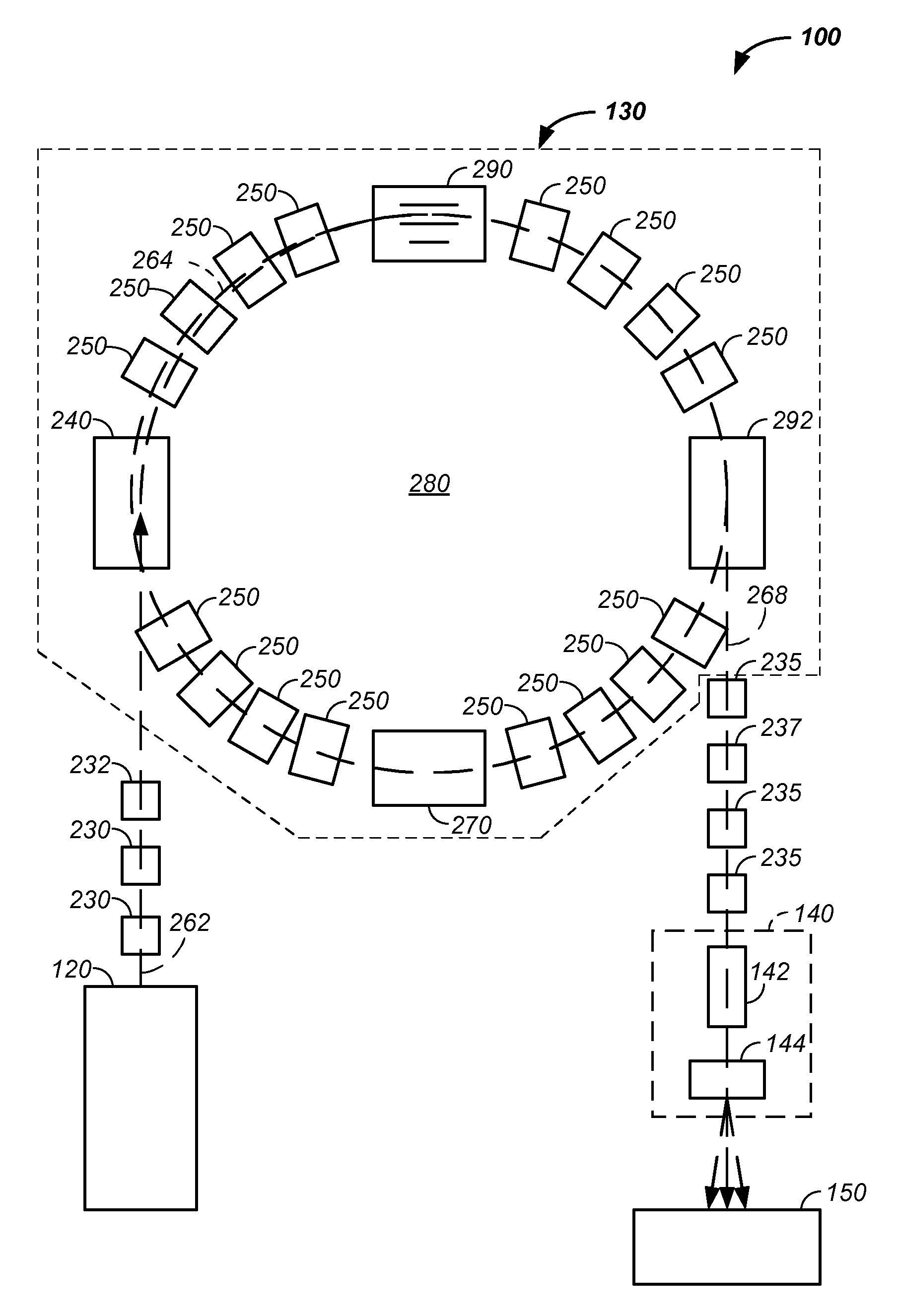
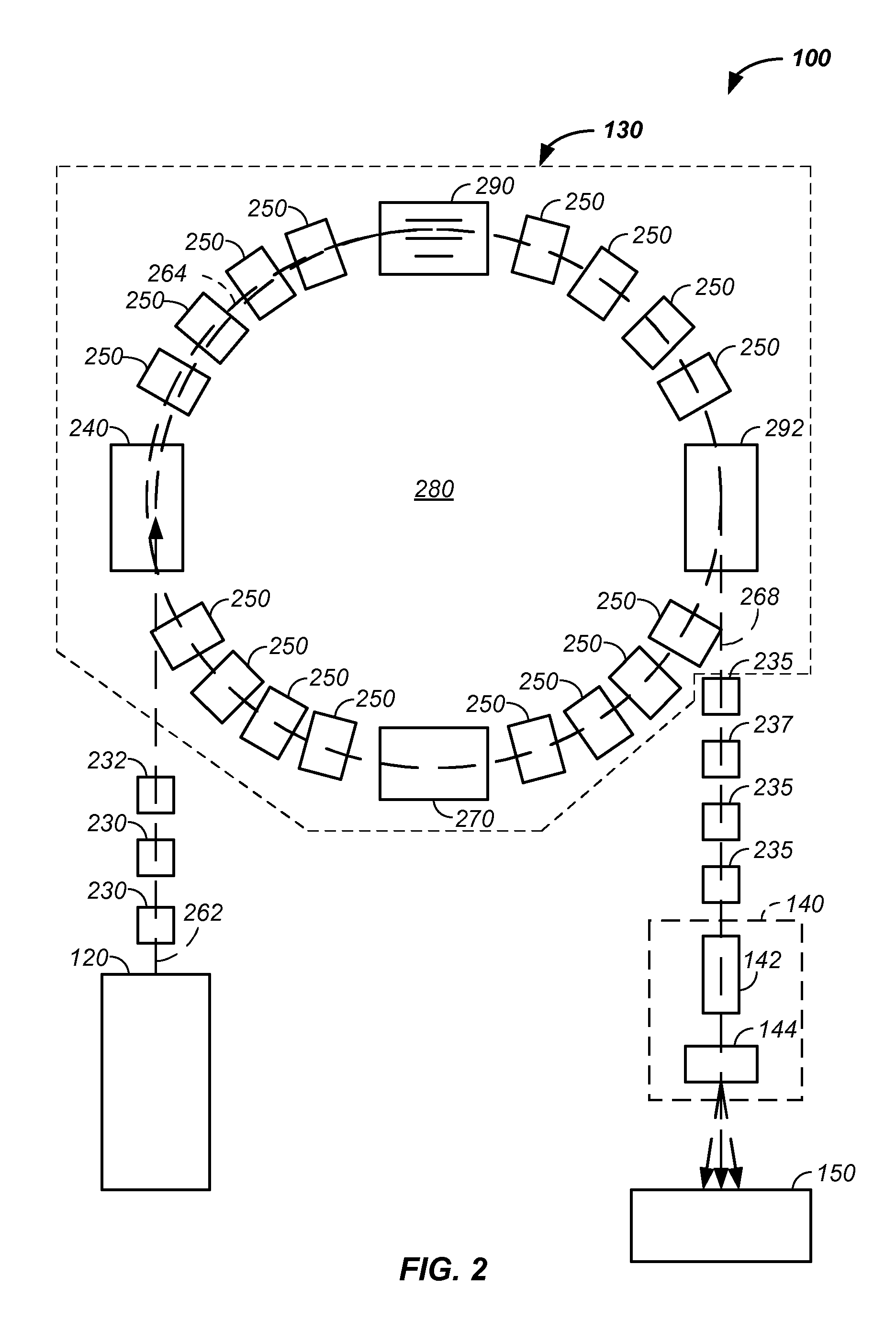
[0185]Still referring to FIG. 4, an exemplary synchrotron 130 is illustrated. A set of magnets control protons in the synchrotron in a repeated cyclic path 264 having a first radius of curvature. Protons in the first path traverse between a first pair of metal plates 412, 414 having an AC frequency voltage applied across the two metal plates. The AC voltage induces an oscillation on some of the protons causing them to pass through a foil material 430 that reduces the speed of the protons. The protons moving at a slower speed have a reduced radius of curvature path 266. The protons having the reduced radius of curvature then pass through a DC field, such as a high voltage field between a second pair of metal plates 414, 416, which directs the protons along a new path. The new path 266 optionally traverses another magnetic field, such as that of a Lamberson magnet, that directs the protons away from the synchrotron.

[0186]Generally, the extraction process takes a proton circulating in ...


PUM


Abstract

The invention comprises a charged particle beam extraction method and apparatus used in conjunction with charged particle beam radiation therapy of cancerous tumors. The system uses a radio-frequency (RF) cavity system to induce betatron oscillation of a charged particle stream. Sufficient amplitude modulation of the charged particle stream causes the charged particle stream to hit a material, such as a foil. The foil decreases the energy of the charged particle stream, which decreases a radius of curvature of the charged particle stream in the synchrotron sufficiently to allow a physical separation of the reduced energy charged particle stream from the original charged particle stream. The physically separated charged particle stream is then removed from the system by use of an applied field and deflector.

Description

CROSS REFERENCES TO RELATED APPLICATIONS[0001]This application claims benefit of:[0002]U.S. provisional patent application No. 61 / 055,395 filed May 22, 2008;[0003]U.S. provisional patent application No. 61 / 137,574 filed Aug. 1, 2008;[0004]U.S. provisional patent application No. 61 / 192,245 filed Sep. 17, 2008;[0005]U.S. provisional patent application No. 61 / 055,409 filed May 22, 2008;[0006]U.S. provisional patent application No. 61 / 203,308 filed Dec. 22, 2008;[0007]U.S. provisional patent application No. 61 / 188,407 filed Aug. 11, 2008;[0008]U.S. provisional patent application No. 61 / ______ filed March 2009 (attorney docket No. PROT0005PR);[0009]U.S. provisional patent application No. 61 / 188,406 filed Aug. 11, 2008;[0010]U.S. provisional patent application No. 61 / 189,815 filed Aug. 25, 2008;[0011]U.S. provisional patent application No. 61 / ______ filed February 2009 (attorney docket No. PROT0009PR);[0012]U.S. provisional patent application No. 61 / 201,731 filed Dec. 15, 2008 (attorney d...

Claims


Application Information

Patent Timeline
Patent Type & Authority Applications(United States)
IPC IPC(8): H01J3/14A61N5/00
CPCA61N5/10H05H13/04H05H7/10A61N2005/1087
Inventor BALAKIN, VLADIMIR
Owner BALAKIN ANDREY VLADIMIROVICH
Why Eureka
Try Eureka