Magnetic resonance imaging apparatus and magnetic resonance imaging method

US20090309592A1Active Publication Date: 2009-12-17TOSHIBA MEDICAL SYST CORP

Image

  • Magnetic resonance imaging apparatus and magnetic resonance imaging method
  • Magnetic resonance imaging apparatus and magnetic resonance imaging method
  • Magnetic resonance imaging apparatus and magnetic resonance imaging method

Examples


Embodiment Construction

[0024]A magnetic resonance imaging apparatus and a magnetic resonance imaging method according to embodiments of the present invention will be described with reference to the accompanying drawings.

(Configuration and Function)

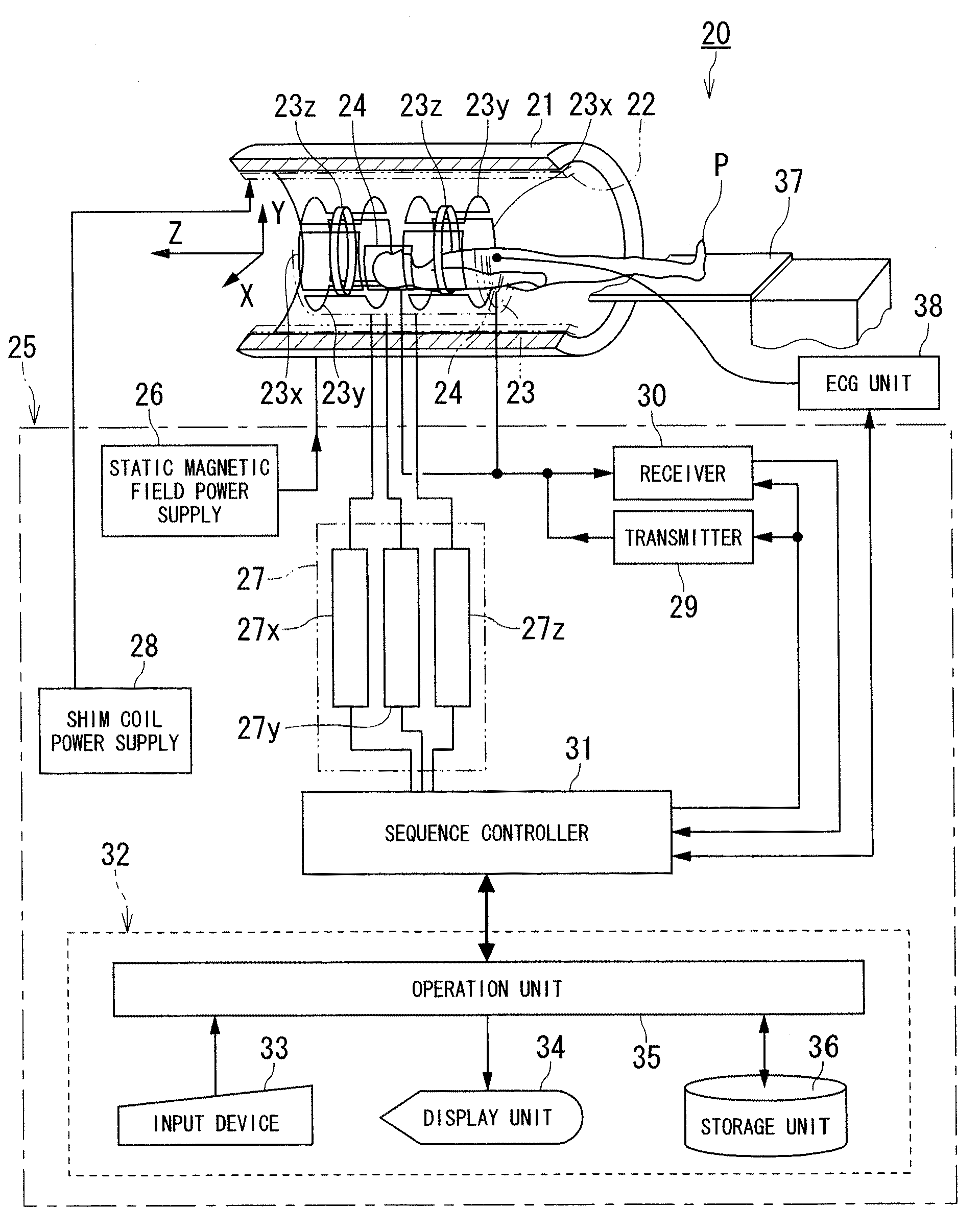
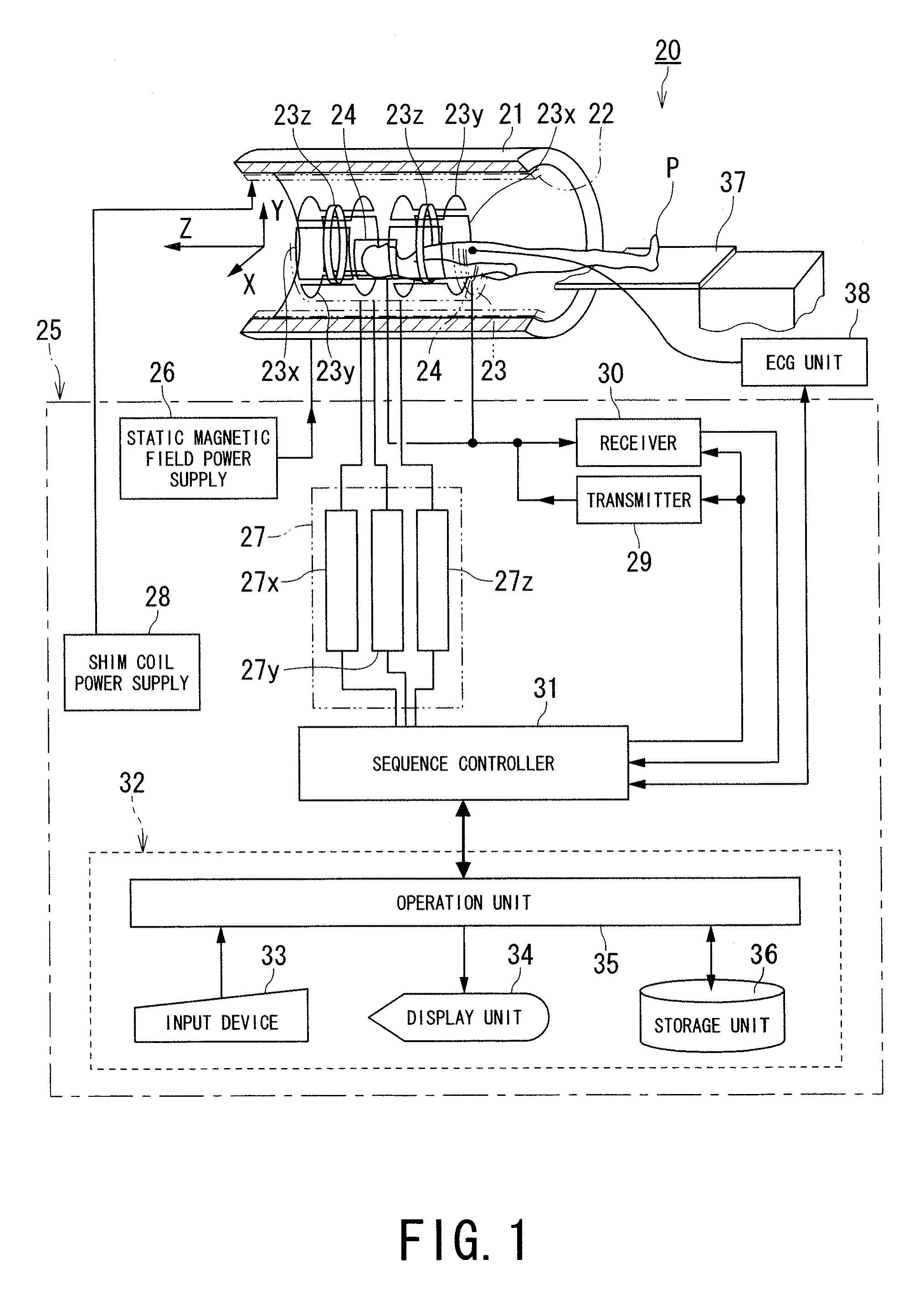
[0025]FIG. 1 is a block diagram showing a magnetic resonance imaging apparatus according to an embodiment of the present invention.

[0026]A magnetic resonance imaging apparatus 20 includes a static field magnet 21 for generating a static magnetic field, a shim coil 22 arranged inside the static field magnet 21 which is cylinder-shaped, a gradient coil 23 and RF coils 24.

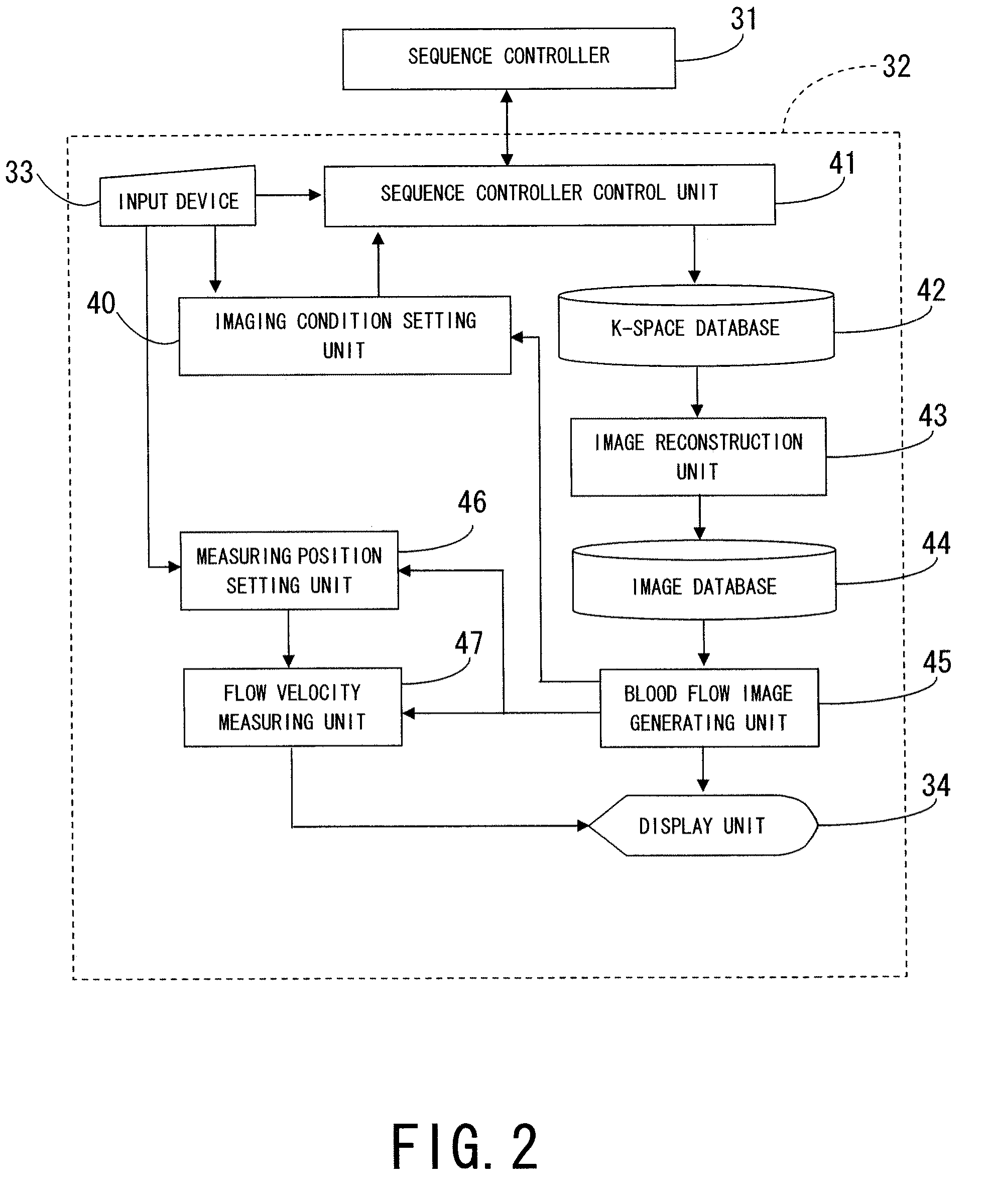
[0027]The magnetic resonance imaging apparatus 20 also includes a control system 25. The control system 25 includes a static magnetic field power supply 26, a gradient power supply 27, a shim coil power supply 28, a transmitter 29, a receiver 30, a sequence controller 31 and a computer 32. The gradient power supply 27 of the control system 25 includes an X-axis gradient power supply 27x, a Y-axis ...


PUM


Abstract

A magnetic resonance imaging apparatus includes a fluid image data acquisition unit and a flow velocity measuring unit. The a fluid image data acquisition unit acquires fluid image data, corresponding to mutually different inversion times, by imaging with applying at least three inversion recovery pulses having the inversion times. The flow velocity measuring unit obtains a flow velocity of fluid based on time variation of a signal intensity depending on the inversion times at each of plural positions and a distance between the plural positions.

Description

BACKGROUND OF THE INVENTION[0001]1. Field of the Invention[0002]The present invention relates to a MRI (magnetic resonance imaging) apparatus and a magnetic resonance imaging method which excite nuclear spin of an object magnetically with a RF (radio frequency) signal having the Larmor frequency and reconstruct an image based on NMR (nuclear magnetic resonance) signals generated due to the excitation, and more particularly, to a magnetic resonance imaging apparatus and a magnetic resonance imaging method which make it possible to measure a flow velocity of fluid.[0003]2. Description of the Related Art[0004]Magnetic Resonance Imaging is an imaging method which excites nuclear spin of an object set in a static magnetic field with a RF signal having the Larmor frequency magnetically and reconstruct an image based on NMR signals generated due to the excitation.[0005]The PS (phase shift) method has been used commonly as a measuring method of a blood flow velocity in the field of magnetic...

Claims


Application Information

Patent Timeline
17 Dec 2009
Publication
US20090309592A1
IPC
G01R33/20; G01F1/56
CPC
G01F1/56; G01R33/5635; G01R33/56308; G01R33/5601
Inventors
FURUDATE, NAOYUKI