Method for manufacturing roller mold

a technology of roller molds and molds, which is applied in the direction of photomechanical treatment originals, photomechanical instruments, photomechanical equipment, etc., can solve the problems of limited quantity of output per unit time, low throughput, and large size of pattern features which can be defined by photolithography techniques

Inactive Publication Date: 2009-12-17
NAT CHENG KUNG UNIV
View PDF5 Cites 17 Cited by
  • Summary
  • Abstract
  • Description
  • Claims
  • Application Information

AI Technical Summary

Benefits of technology

[0007]Therefore, one objective of the present invention is to provide a method for manufacturing a roller mold, which can ...

Problems solved by technology

Currently, due to the optical diffraction limit, the size of the pattern feature, which the photolithography technique can define, is limited seriously.
However, the micro/nano-imprinting apparatus applying the commercial micro/nano-imprinting technique needs long imprinting time, so that the quantity of output per unit time is less, and the throughput i...

Method used


Image

  • Method for manufacturing roller mold
  • Method for manufacturing roller mold
  • Method for manufacturing roller mold

Examples


Embodiment Construction

[0017]The present invention discloses a method for manufacturing a roller mold. In order to make the illustration of the present invention more explicit, the following description is stated with reference to FIGS. 1A through 2F.

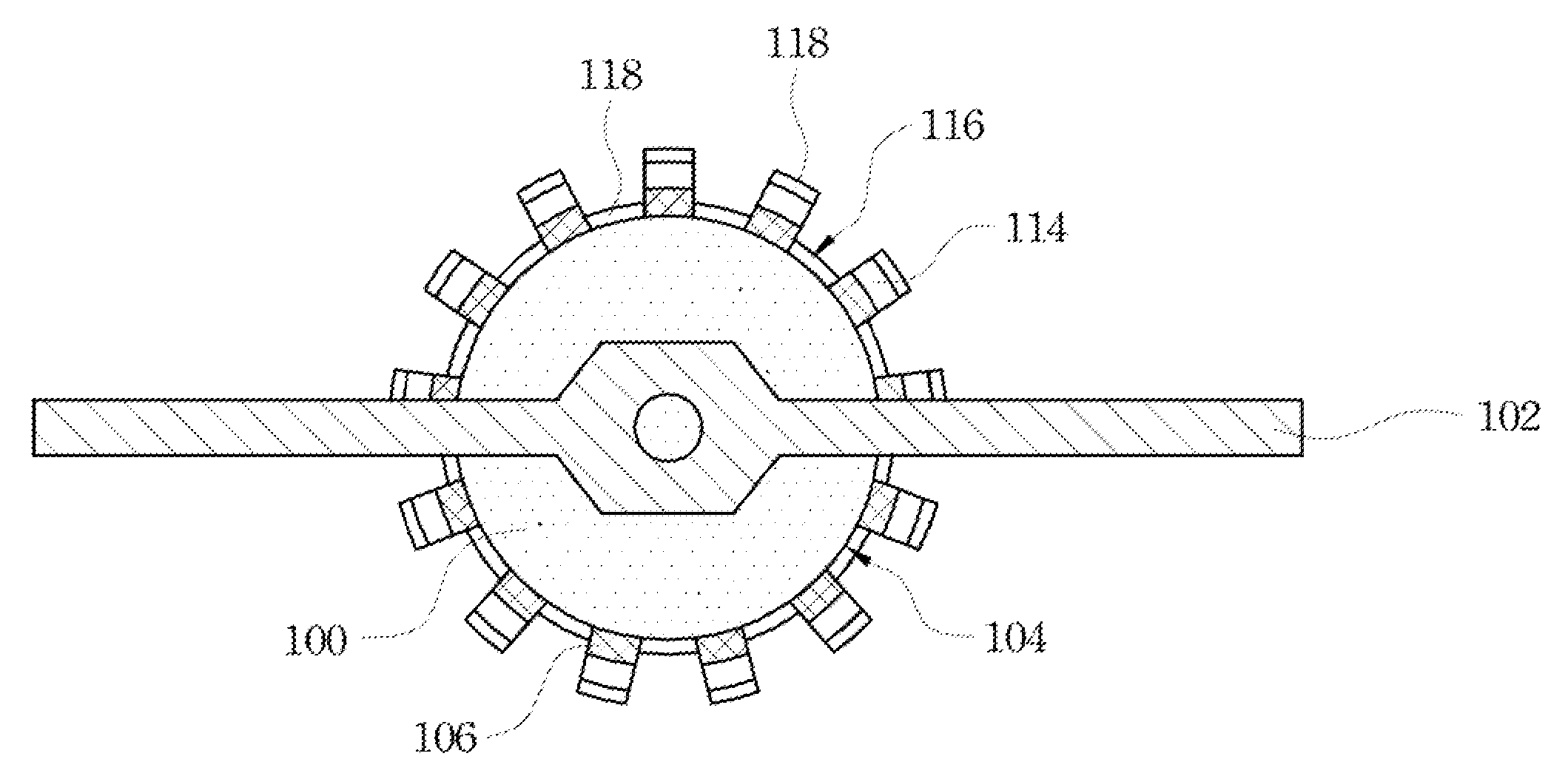
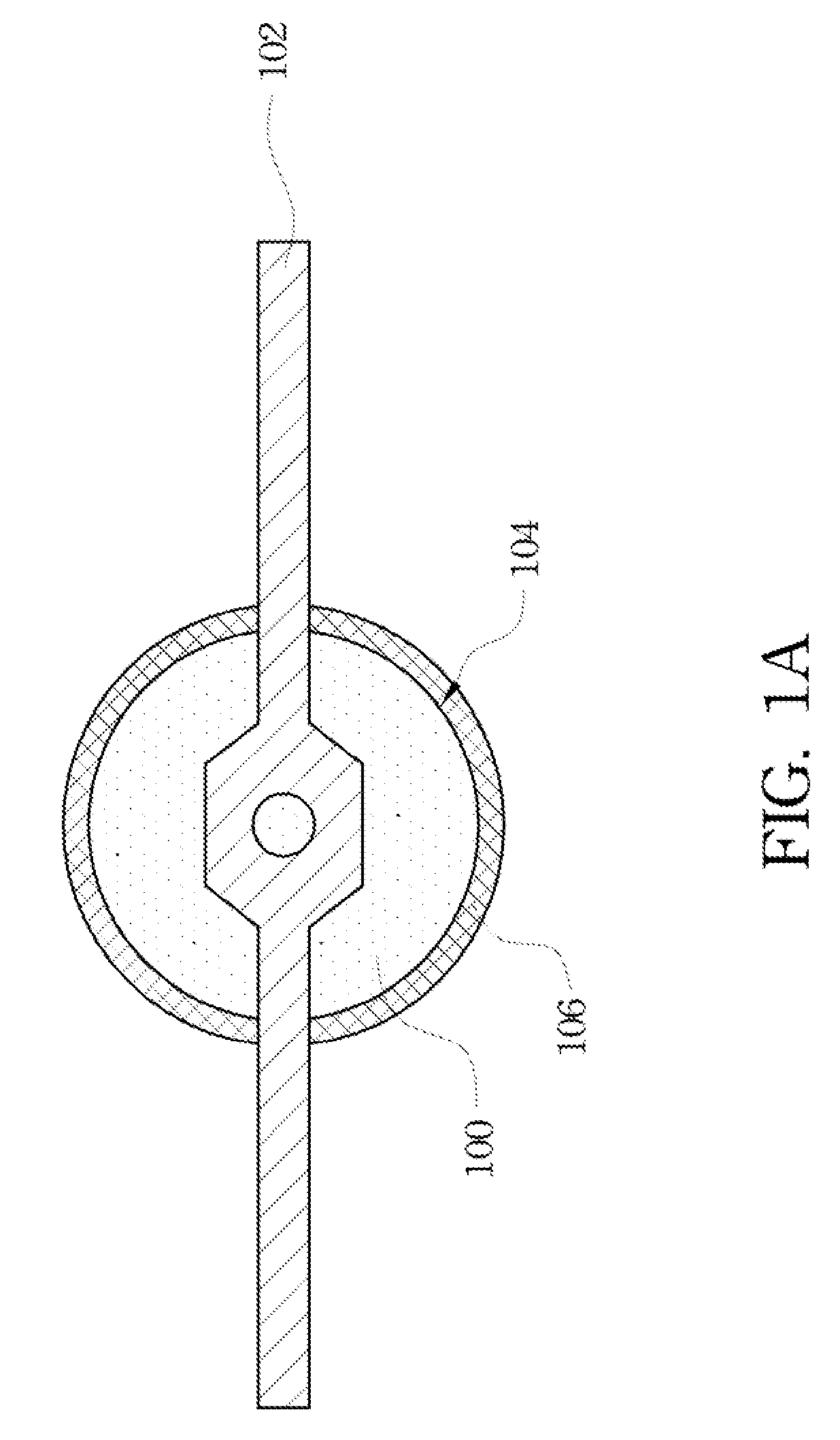
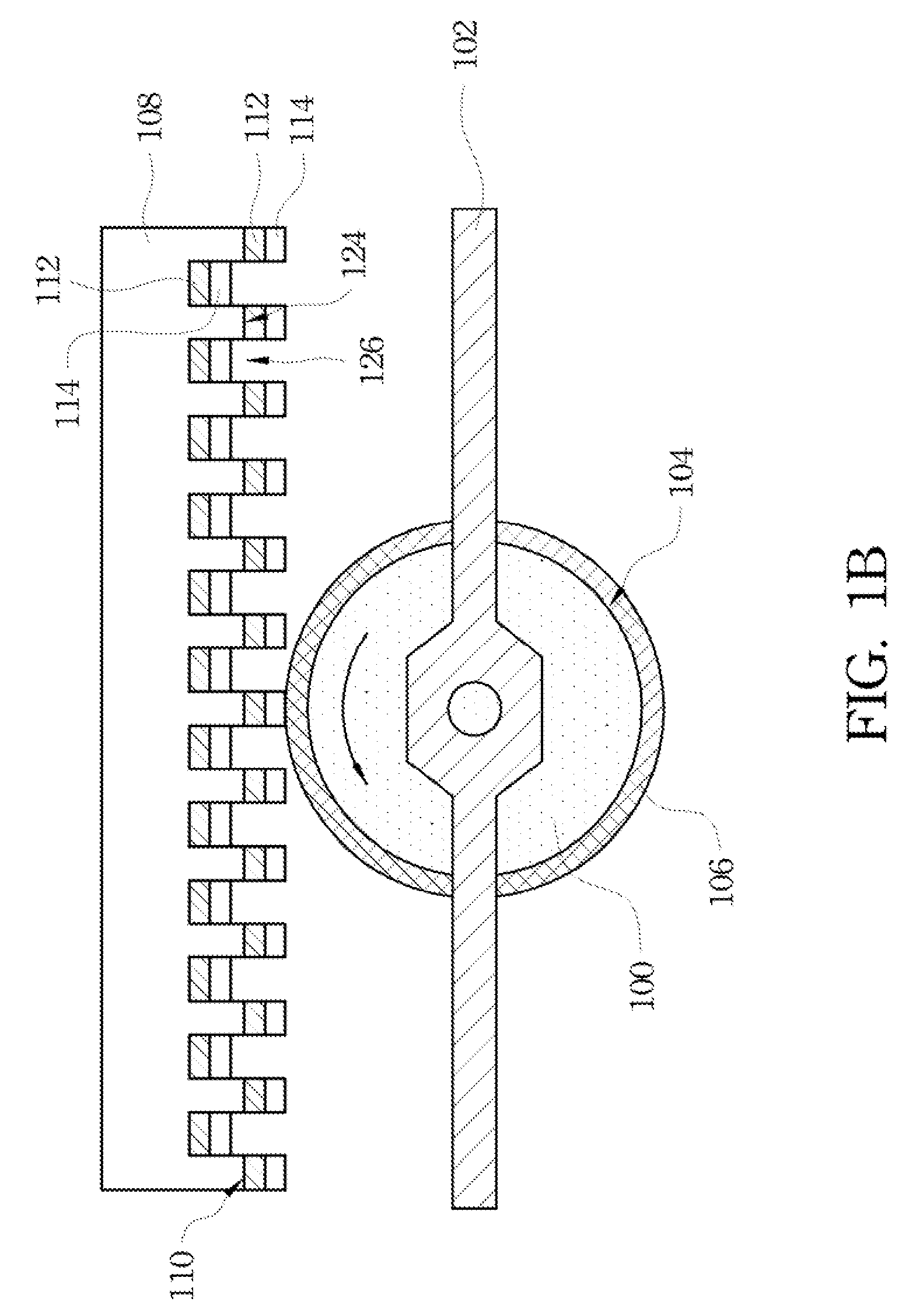
[0018]Refer to FIGS. 1A through 1F. FIGS. 1A through 1F are schematic flow diagrams showing a process for manufacturing a roller mold in accordance with a preferred embodiment of the present invention. In one exemplary embodiment, in the fabrication of a roller mold, a body 100 is firstly provided. The body 100 may be horizontally mounted on a carrier 102 selectively, wherein the body 100 is a cylinder. The material of the body 100 may be, for example, glass, quartz, or metal. A polishing treatment may be performed on a cambered surface 104 of the body 100 to make the body 100 have a smooth cambered surface 104. Then, a photoresist layer 106 is formed on the cambered surface 104 of the body 100 by a spray method with an airbrush for example. The photoresist l...


PUM

PropertyMeasurementUnit
Thicknessaaaaaaaaaa
Flexibilityaaaaaaaaaa

Abstract

A method for manufacturing a roller mold is described, including the following steps. A body is provided, wherein the body is a cylinder. A photoresist layer is formed to completely cover a cambered surface of the body. A mold including a pattern structure including a convex portion and a concave portion is provided, and the convex portion and the concave portion are covered with a transferred pattern layer. The mold is pressed on the photoresist layer. The body is rolled to transfer the transferred pattern layer on the convex portion onto the photoresist layer. The mold is removed. An UV light exposure step is performed on an exposed portion of the photoresist layer to transfer a pattern of the transferred pattern layer to the photoresist layer. The exposed portion of the photoresist layer is removed to expose a portion of the cambered surface of the body. A structure layer is formed on the portion of the cambered surface and the transferred pattern layer. The photoresist layer, and the structure layer and the transferred pattern layer on the photoresist layer are removed.

Description

RELATED APPLICATIONS[0001]This application claims priority to Taiwan Application Serial Number 97121936, filed Jun. 12, 2008, which is herein incorporated by reference.FIELD OF THE INVENTION[0002]The present invention relates to a method for manufacturing an imprinting mold, and more particularly to a method for manufacturing a roller mold.BACKGROUND OF THE INVENTION[0003]Currently, due to the optical diffraction limit, the size of the pattern feature, which the photolithography technique can define, is limited seriously. Therefore, the developing potential of a micro / nano-imprinting technology has attracted much attention, and has been regarded as one possible method that can surpass and replace the conventional micro / nano photolithography technology.[0004]Currently, many micro / nano-imprinting techniques have been developed. However, the micro / nano-imprinting apparatus applying the commercial micro / nano-imprinting technique needs long imprinting time, so that the quantity of output...

Claims


Application Information

Patent Timeline
IPC IPC(8): G03F7/20
CPCB29C33/3878B29C33/424G03F7/2018B82Y40/00G03F7/0002B82Y10/00
Inventor LEE, YUNG-CHUNCHIU, CHENG-YU
Owner NAT CHENG KUNG UNIV
Why Eureka
Try Eureka