Power supply system, vehicle provided with the same, temperature rise control method of power storage device, and computer-readable recording medium with program recorded thereon for causing computer to execute temperature rise control of power storage device
- Summary
- Abstract
- Description
- Claims
- Application Information
AI Technical Summary
Benefits of technology
Problems solved by technology
Method used
Image
Examples
first embodiment
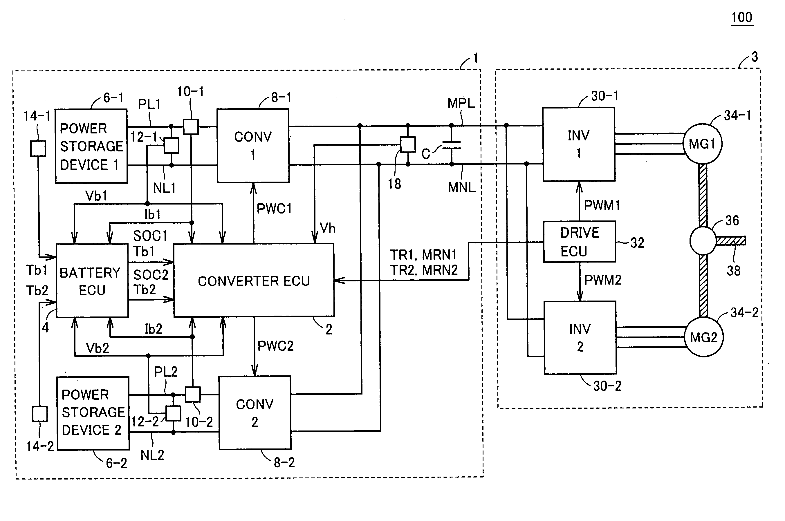
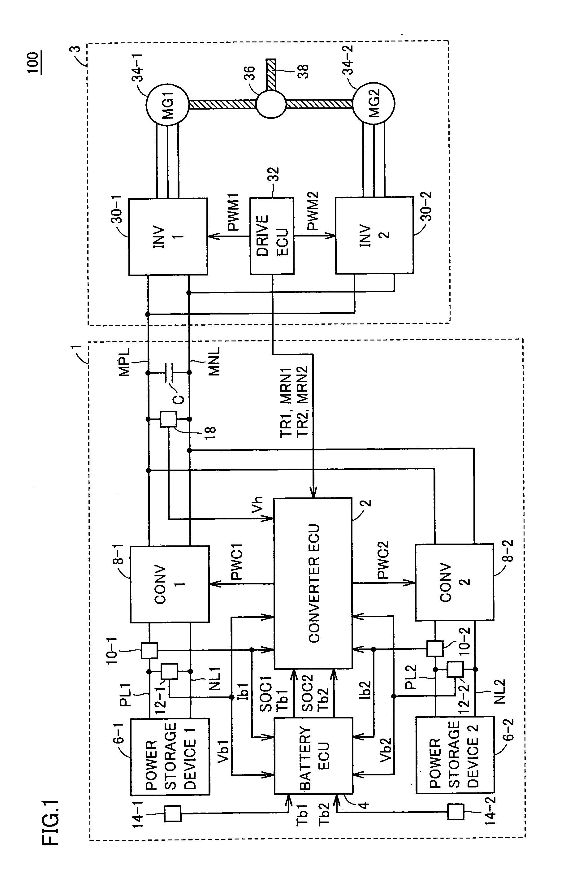
[0096]FIG. 1 is an entire block diagram showing a vehicle according to a first embodiment of the present invention. With reference to FIG. 1, a vehicle 100 is provided with a power supply system 1, and a drive force generator unit 3. The drive force generator unit 3 includes inverters 30-1 and 30-2, motor generators 34-1 and 34-2, a mechanical power transmission mechanism 36, a drive shaft 38, and a drive ECU (Electronic Control Unit) 32.
[0097]Inverters 30-1 and 30-2 are connected to a main positive bus MPL and a main negative bus MNL in parallel. Thus, inverters 30-1 and 30-2 convert a drive electric power (DC electric power) supplied from power supply system 1 to an AC electric power and output it to motor generators 34-1 and 34-2, respectively. In addition, inverters 30-1 and 30-2 convert an AC electric power generated from motor generators 34-1 and 34-2 to a DC power and output it to power supply system 1 as a regenerative electric power.
[0098]Each of inverters 30-1 and 30-2 is ...
second embodiment
[0173]According to a second embodiment, when a voltage of a power storage device gets out of the range of upper and lower limits, a duty command of a corresponding converter is corrected such that the voltage of the power storage device falls within the range of the upper and lower limits, and a target voltage of the converter is corrected to prevent the voltage of the power storage device from getting out of the range of the upper and lower limits again.
[0174]Entire constitutions of a vehicle and a converter ECU according to the second embodiment is the same as that of vehicle 100 and converter ECU 2 shown in FIGS. 1 and 3.
[0175]FIG. 7 is a detailed functional block diagram showing a temperature rise control unit according to the second embodiment. With reference to FIG. 7, a temperature rise control unit 44B includes a first control unit 50-1B, a second control unit 50-2B, and a target value setup unit 80B.
[0176]As compared with the constitution of first control unit 50-1A shown i...
third embodiment
[0191]While the temperature rise control unit is configured by the voltage control system in the embodiments 1 and 2, a temperature rise control unit is configured by a current control system in a third embodiment.
[0192]Entire constitutions of a vehicle and a converter ECU according to the third embodiment is the same as those of vehicle 100 and converter ECU 2 shown in FIGS. 1 and 3.
[0193]FIG. 9 is a functional block diagram showing a temperature rise control unit according to the third embodiment. With reference to FIG. 9, a temperature rise control unit 44C includes a first control unit 50-1C, a second control unit 50-2C, and a target value setup unit 80C.
[0194]As compared with the constitution of first control unit 50-1A shown in FIG. 6, first control unit 50-1C includes a subtraction unit 102-1 and PI control unit 104-1, instead of subtraction unit 52-1 and PI control unit 54-1.
[0195]Subtraction unit 102-1 subtracts current value Ib1 from a target current IR1 outputted from tar...
PUM
| Property | Measurement | Unit |
|---|---|---|
| temperature Tth | aaaaa | aaaaa |
| electric power | aaaaa | aaaaa |
| voltage | aaaaa | aaaaa |
Abstract
Description
Claims
Application Information
 - R&D
- Intellectual Property
- Life Sciences
- Materials
- Tech Scout
- Unparalleled Data Quality
- Higher Quality Content
- 60% Fewer Hallucinations
Browse by: Latest US Patents, China's latest patents, Technical Efficacy Thesaurus, Application Domain, Technology Topic, Popular Technical Reports.
© 2025 PatSnap. All rights reserved.Legal|Privacy policy|Modern Slavery Act Transparency Statement|Sitemap|About US| Contact US: help@patsnap.com


