Atomic oscillator

Active Publication Date: 2009-12-24
MICROCHIP TECH INC
View PDF4 Cites 20 Cited by
  • Summary
  • Abstract
  • Description
  • Claims
  • Application Information

AI Technical Summary

Benefits of technology

[0015]An advantage of the present invention is to provide an atomic oscillator that includes a gas cell, of which degradation of heating efficiency is suppressed, has high accuracy, and can be miniaturized.
[0017]An atomic oscillator according to an aspect of the invention includes: a gas cell in which a gaseous metal atom is sealed; heating units heating the gas cell to a controlled temperature and being a first heater and a second heater; a light source of exciting light exciting the metal atom in the gas cell; a light detecting unit detecting the exciting light which has passed through the gas cell; a substrate including at least a temperature controlling circuit for the heating units; a first heater wiring coupling the first heater and the substrate; a second heater wiring coupling the second heater and the substrate; and a third heater wiring coupling the first heater and the second heater. In the oscillator, the gas cell includes a cylindrical portion; and windows which constitute an incident surface and an emitting surface on an optical path of the exciting light. Further, the first heater and the second heater are respectively formed on the windows at an incident surface side and an emitting surface side and made of transparent heating materials.
[0018]According to this structure, since the first heater and the second heater are coupled with the substrate respectively through the first heater wiring and the second heater wiring as the heating units which are formed on the windows of the gas cell, the first heater and the second heater can be driven in a manner coupled with the substrate in series. Thus, the number of heater wirings is smaller in this structure than a case where the first heater and the second heater are independently coupled with the substrate. Therefore, degradation of thermal efficiency of the heaters, which is caused by leak of thermal energy from the heater wirings, can be suppressed and a wiring space of the heater wirings can be reduced. Accordingly, such an atomic oscillator that has a stable oscillation property, is miniaturized, and consumes low amounts of power can be provided.
[0019]In the atomic oscillator of the aspect, the third heater wiring may be made of a material same as a material of the first heater and the second heater.
[0020]According to this structure, the third heater wiring can be efficiently formed by the same equipment as that used in forming the first heater and the second heater in the gas cell.

Problems solved by technology

Here, when atomic concentration within the gas cell is varied in the atomic oscillator, a degree of absorption of light to the atomic gas is varied, causing an error of detection of the atomic resonance or an impossibility of detection.
However, due to a demand of miniaturizing an electronic apparatus including an atomic oscillator is increased, the atomic oscillator needs to be miniaturized.
Therefore, as the number of heater wirings is increased, heating efficiency of the gas cell may be deteriorated to increase power consumption, or temperature distribution may occur in the gas cell to deteriorate accuracy of the atomic oscillator.
Further, as the number of the heater wirings is increased, a wiring space is enlarged to make it hard to miniaturize the atomic oscillator and the controlling circuit substrate disadvantageously has a complex circuit structure.

Method used


Image

  • Atomic oscillator
  • Atomic oscillator
  • Atomic oscillator

Examples


first modification

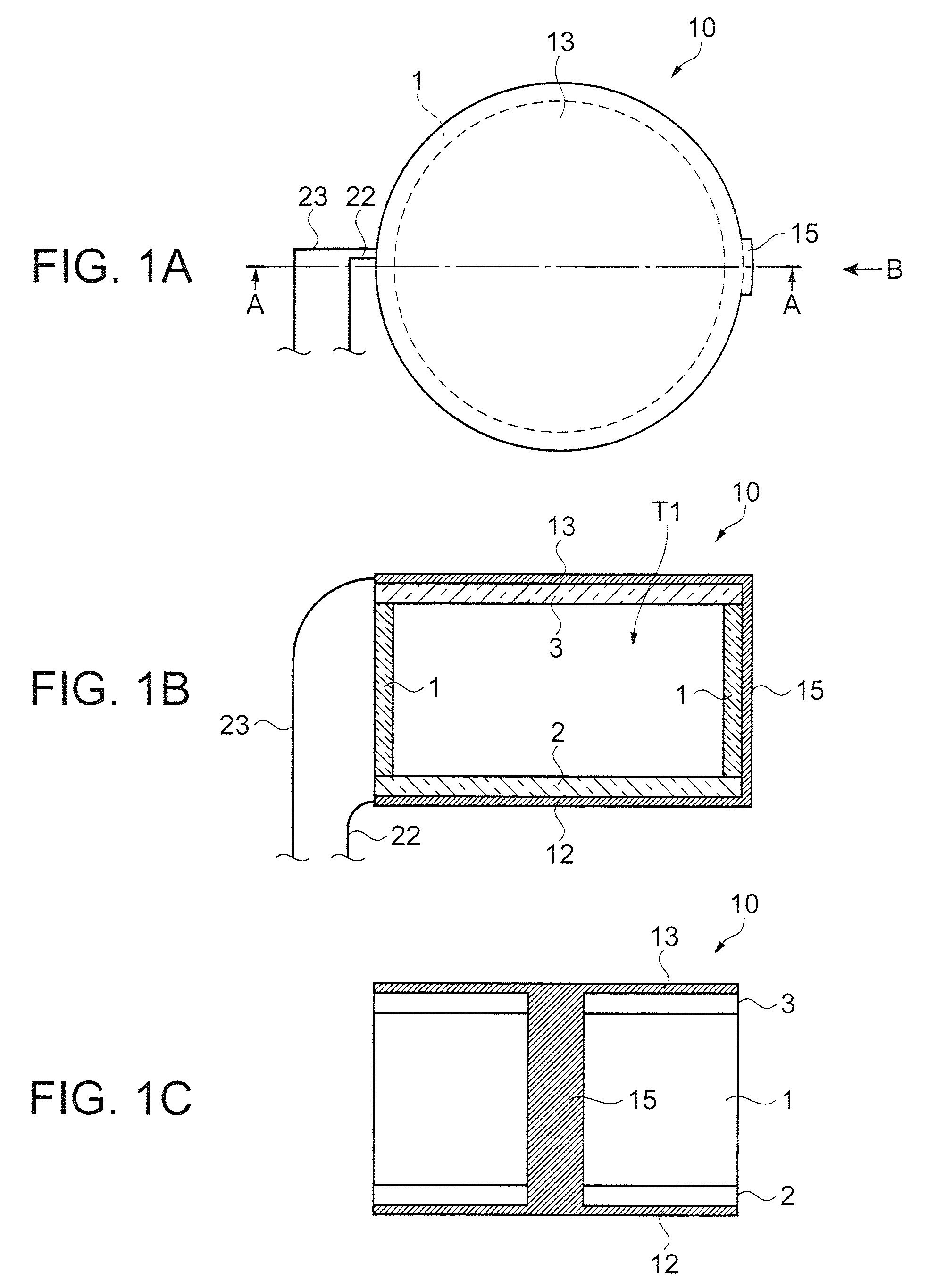
[0060]The third heater wiring 15 having a shape shown in FIGS. 1A to 1C is formed as a heater wiring, which couples the first heater 12 and the second heater 13, of the gas cell 10 in the embodiment, but the shape of the heater wiring is not limited to it. The heater wiring may have any shape as long as the heater wiring can couple the first heater 12 and the second heater 13 while securing a constant thermal efficiency of the heaters 12 and 13.

[0061]FIG. 3 is a schematic lateral view showing a gas cell, which is viewed from the same direction as FIG. 1C, of a first modification for explaining an example of a heater wiring having different shape from the third heater wiring 15 of the above embodiment. Here, elements same as those in the embodiment will be given the same reference numbers and their explanation will be omitted.

[0062]In a gas cell 60 shown in FIG. 3, a first heater 62 and a second heater 63 respectively formed on outer surfaces of the windows 2 and 3 and composed of tr...

second modification

[0064]In the embodiment and the first modification, the third heater wiring 15 or the third wirings 65 are used only for electrically coupling the first heater 12 or 62 and the second heater 13 or 63. However, the third heater wiring can be used as a third heater heating the gas cell depending on its material or shape.

[0065]FIG. 4 is a schematic lateral view showing a gas cell viewed from the same direction as FIG. 1C for explaining that the third heater wiring is used as a third heater. Here, elements same as those in the embodiment and the first modification will be given the same reference numbers and their explanation will be omitted.

[0066]In a gas cell 70 shown in FIG. 4, a first heater 72 and a second heater 73 respectively formed on outer surfaces of the windows 2 and 3 and composed of transparent electrode films made of ITO, for example, are coupled by a heater wiring 75 having large width and formed on the cylindrical portion 1. The third heater wiring 75 is composed of a t...

third modification

[0068]In the embodiment, the first modification, and the second modification, the third heater wiring(s) 15, 65, or 75 is composed of a transparent electrode film made of ITO, for example, as is the case with the first heater 12 or 62 and the second heater 13 or 63. However, the third heater wiring may be made of a conductive material which is different from the material of the first heater and the second heater. FIG. 5 is a schematic lateral view showing a gas cell viewed from the same direction as FIG. 1C for explaining that the third heater wiring is made of a material which is different from the material of the first heater and the second heater. Here, elements same as those in the embodiment and the first and second modifications will be given the same reference numbers and their explanation will be omitted.

[0069]This gas cell 80 shown in FIG. 5 includes a first heater 82 and a second heater 83 that are respectively formed on outer surfaces of the windows 2 and 3 and are compos...


PUM


Abstract

An atomic oscillator includes: a gas cell in which a gaseous metal atom is sealed; heating units heating the gas cell to a predetermined temperature and being a first heater and a second heater; a light source of exciting light exciting the metal atom in the gas cell; a light detecting unit detecting the exciting light which has passed through the gas cell; a substrate including at least a temperature controlling circuit for the heating units; a first heater wiring coupling the first heater and the substrate; a second heater wiring coupling the second heater and the substrate; and a third heater wiring coupling the first heater and the second heater. In the atomic oscillator, the gas cell includes a cylindrical portion; and windows which respectively seal openings at both ends of the cylindrical portion and constitute an incident surface and an emitting surface on an optical path of the exciting light. The first heater and the second heater are respectively formed on the windows at an incident surface side and an emitting surface side and made of transparent heating materials.

Description

BACKGROUND[0001]1. Technical Field[0002]The present invention relates to an atomic oscillator, in particular, relates to an atomic oscillator that includes a gas cell, of which degradation of heating efficiency is suppressed, has high accuracy, and can be miniaturized.[0003]2. Related Art[0004]Atomic oscillators using alkali metals such as rubidium and cesium need to keep alkali metal atoms in a vapor state with buffer gas in a gas cell when the oscillators use energy transition of the atoms. Therefore, the oscillators operate while maintaining the gas cell, in which the atoms are sealed, at a high temperature. An operating principle of the atomic oscillators is broadly classified into a double resonance method utilizing light exciting alkali metal atoms and micro waves (refer to JP-A-10-284772, as a first example), and a method utilizing quantum interference effect (hereinafter, refereed to as coherent population trapping: CPT) produced by two kinds of interfering light (refer to U...

Claims


Application Information

Patent Timeline
IPC IPC(8): H01S1/06
CPCG04F5/145
Inventor CHINDO, KOJIAOYAMA, TAKU
Owner MICROCHIP TECH INC
Why Eureka
Try Eureka