Liquid ejection head and method of manufacturing the liquid ejection head

Inactive Publication Date: 2009-12-24
CANON KK
View PDF14 Cites 23 Cited by
  • Summary
  • Abstract
  • Description
  • Claims
  • Application Information

AI Technical Summary

Benefits of technology

[0015]Then, in view of the above-described circumstances, it is an object of the present invention to provide a print head that simplifies the manufacture process of a print head and

Problems solved by technology

Moreover, in the heat generating portion at the time of ejecting ink, a bubbling portion affecting bubbling is exposed to a high temperature due to the heating of the heating resistor in the heat generating portion.
However, in the case where the protective layer formed from a noble metal is adopted as the protective layer arranged adjacent to the ink reservoir, there is a problem that the adhesion between the protective layer formed from a noble metal and a flow passage forming member is poor.
Accordingly, if the adhesion between the protective

Method used


Image

  • Liquid ejection head and method of manufacturing the liquid ejection head
  • Liquid ejection head and method of manufacturing the liquid ejection head
  • Liquid ejection head and method of manufacturing the liquid ejection head

Examples


first embodiment

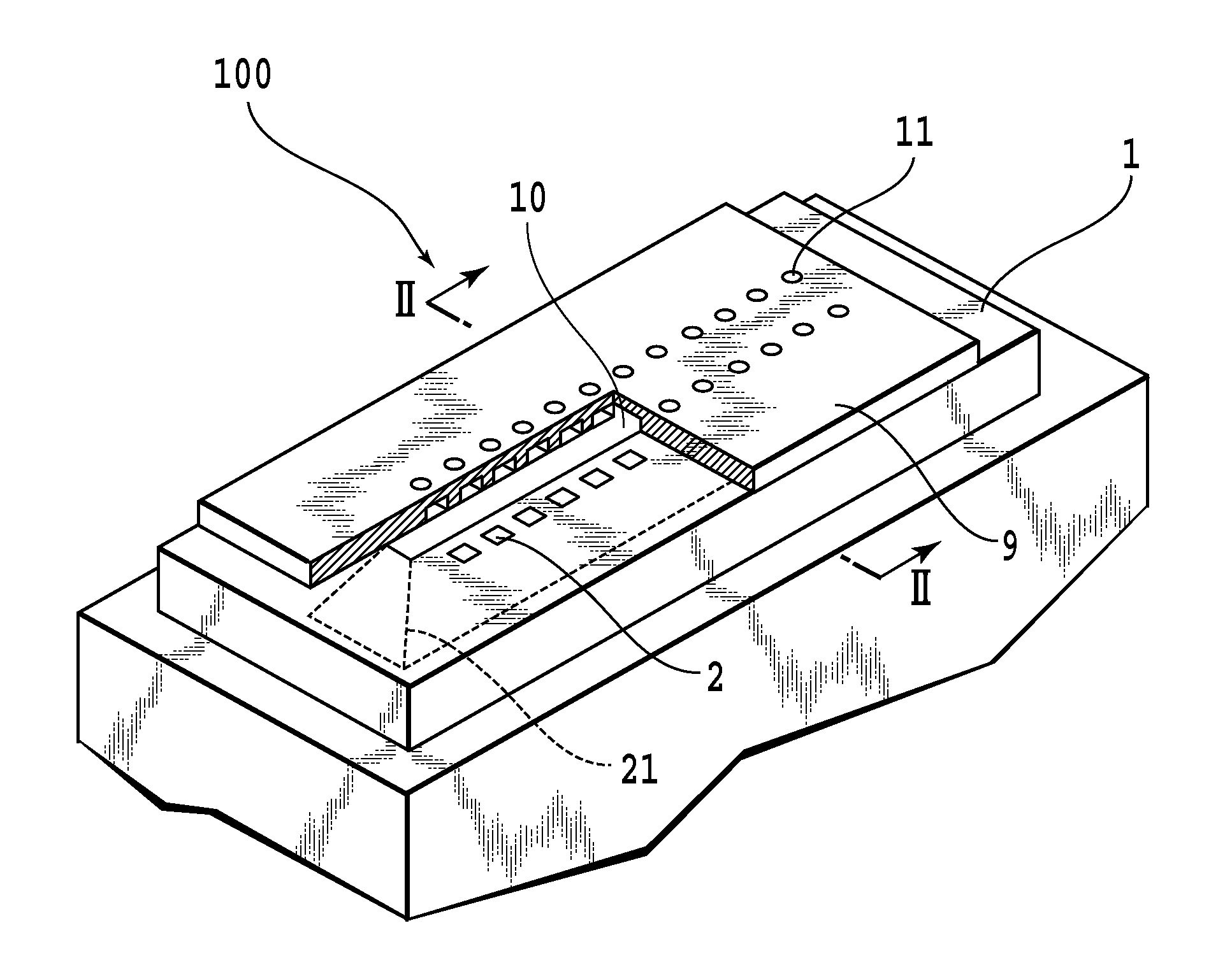
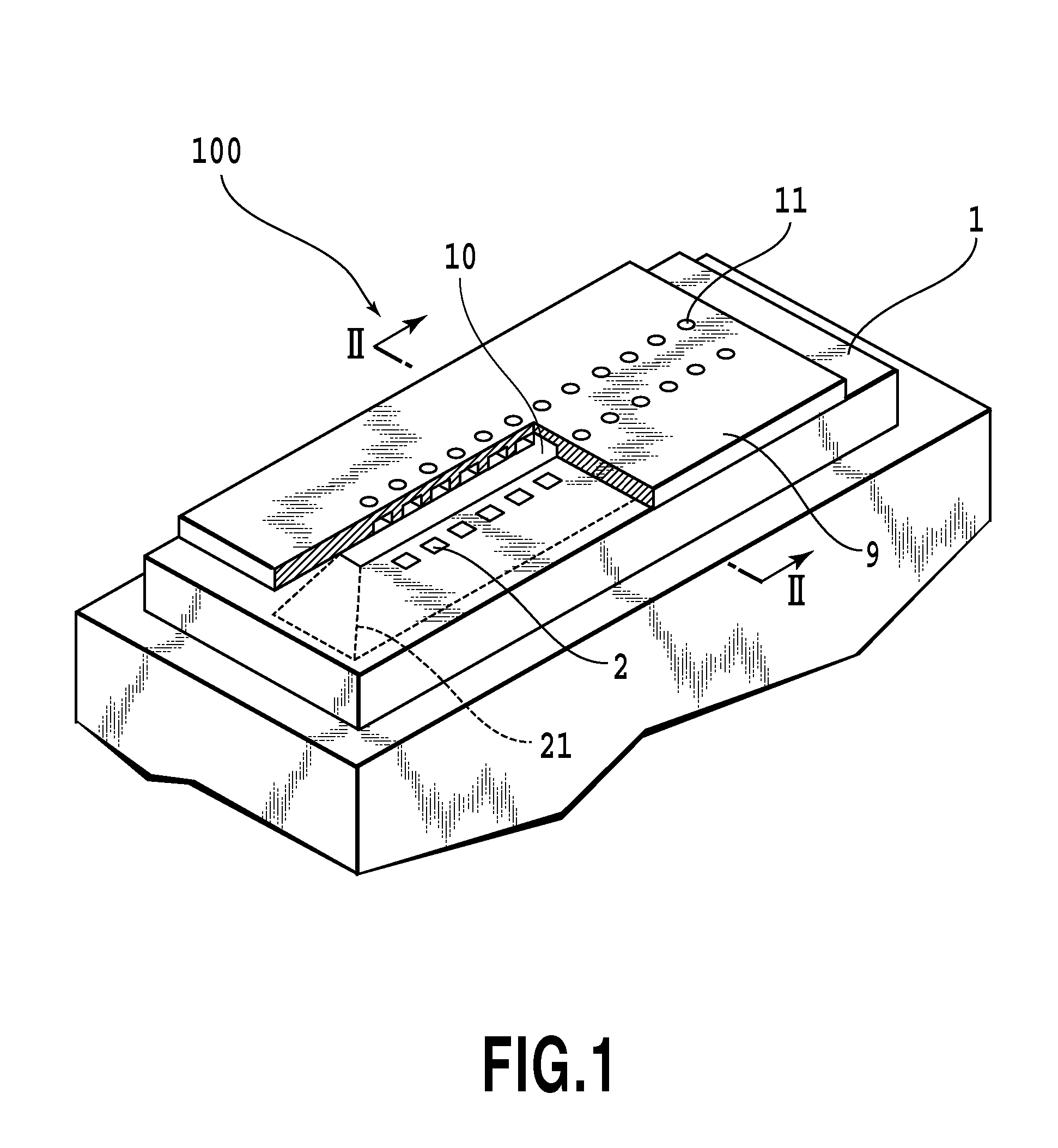
[0029]FIG. 1 shows a perspective view of a print head 100 according to a first embodiment of the present invention. The print head 100 includes a substrate 1 having a heat generating portion 2 arranged therein, and a flow passage forming member 9 having a ejection port 11 formed therein. Semiconductor elements, such as switching transistors for selectively driving the heat generating portion 2, or the like, are arranged in the substrate 1. Then, the substrate 1 and the flow passage forming member 9 are joined together, whereby a liquid chamber 10 capable of storing ink as a liquid is defined therebetween. Ink is stored in the liquid chamber 10, and heat energy is transferred to this ink by the heat generating portion 2, whereby the ink is ejected from the ejection port 11. Moreover, in the substrate 1, an ink supply port 21 for supplying ink to the print head 100 is formed so as to communicate with the liquid chamber 10. Ink is supplied to the print head 100 from a non-illustrated i...

second embodiment

[0059]Next, a second embodiment for implementing the present invention is described. The description of portions having the same configurations as those of the first embodiment are omitted and only portions having different configurations will be described.

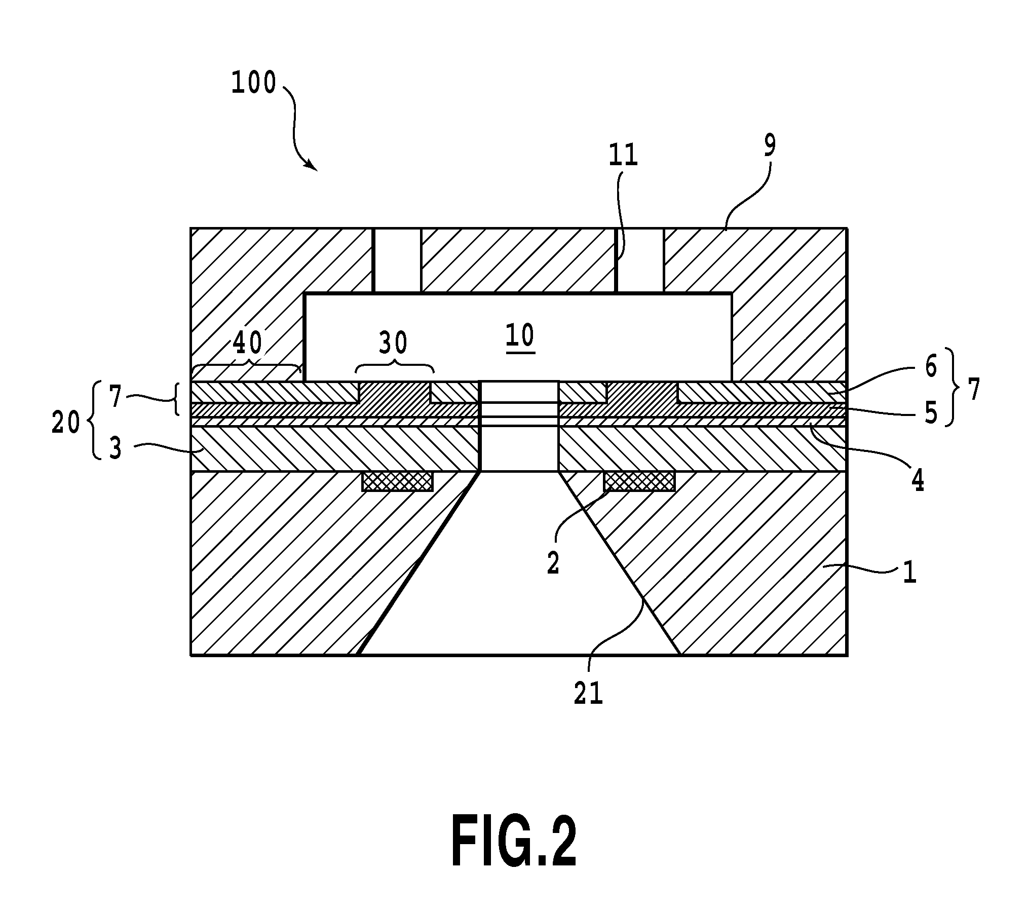
[0060]In the first embodiment, the second protective layer 7 is formed in two layers consisting of the iridium portion 5 on the rear surface side opposite to the flow passage forming member and the iridium oxide portion 6 on the flow passage forming member side. Then, the protective layer reducing step is performed by heating the portion corresponding to the heat generating portion 2 in the state where the second iridium portion 5 and the iridium oxide portion 6 in the second protective layer 7 are overlapped with each other. On the other hand, in the second embodiment, a second protective layer 8, the whole of which is made of iridium oxide, is formed via the adhesion layer 4 on the flow passage forming member side of the first p...


PUM

PropertyMeasurementUnit
Volumeaaaaaaaaaa
Electric potential / voltageaaaaaaaaaa
Contentaaaaaaaaaa

Abstract

To provide a print head that simplifies the manufacture process of a print head and reduces the manufacturing cost while preventing the peeling-off between a substrate and a flow passage forming member in the print head, and a method of manufacturing the print head. In the print head of the present invention, a protective layer is formed in a flow passage forming member side portion in a heat generating portion 2. The protective layer 20 contains a noble metal. Then, in the flow passage forming member side portion in the protective layer 20, the surface thereof is made of an oxide of a noble metal except in a portion corresponding to the heat generating portion 2, while in the portion corresponding to the heat generating portion 2 on the flow passage forming member side in the protective layer 20, the surface thereof is made of the noble metal.

Description

BACKGROUND OF THE INVENTION[0001]1. Field of the Invention[0002]The present invention relates to a liquid ejection head for printing by ejecting liquid, and a method of manufacturing the liquid ejection head, and specifically relates to an ink jet print head for printing by ejecting ink to a printing medium, and a method of manufacturing the ink jet print head.[0003]2. Description of the Related Art[0004]Usually, a liquid ejection head (hereinafter, also referred to as a print head) used in an inkjet printing apparatus includes an ejection port, a flow passage communicating with this ejection port, and a heat generating portion that generates, in this flow passage, heat energy used to eject ink. The heat generating portion comprises a heating resistor and an electrode for supplying electric power to the heating resistor. Usually, in the print head, in order to prevent electricity from conducting from the heat generating portion to ink, the heat generating portion is covered with a p...

Claims


Application Information

Patent Timeline
IPC IPC(8): B41J2/05B05D3/00C23C14/34
CPCB41J2/14129B41J2/1603B41J2/1621Y10T29/49117Y10T29/49082Y10T29/49346Y10T29/49083Y10T29/49163
Inventor ISHIDA, YUZURUMATSUI, TAKAHIROSAITO, ICHIRO
Owner CANON KK
Why Eureka
Try Eureka