Lighting device

a technology of light source and light source, which is applied in the direction of lighting and heating apparatus, semiconductor devices for light sources, and light utilization efficiency deterioration to lower light intensity, and can solve the problems of heat generation that can be significant, difficult and sometimes impossible to obtain sufficient light intensity, and achieves efficient heat dissipation, prolonging service life, and maintaining high light intensity without deterioration of light emission efficiency of the devi

Inactive Publication Date: 2009-12-24
STANLEY ELECTRIC CO LTD
View PDF5 Cites 23 Cited by
  • Summary
  • Abstract
  • Description
  • Claims
  • Application Information

AI Technical Summary

Benefits of technology

[0017]The lighting device can be suitably used for efficiently dissipating heat generated by the semiconductor light emitting device to which a large current must be supplied. This configuration can stably maintain a high light intensity without the light emission efficiency of the device deteriorating. Furthermore, the device's service lifetime can be extended. As the inside temperature distribution can be made more even, the fogging of the inner surface of the outer lens can be prevented. Furthermore, as the temperature of the outer lens can be caused to rise, snow adherence on the outer lens can be simultaneously prevented.
[0018]In the presently disclosed subject matter, the parabolic reflector can reflect light that cannot be reflected by the elliptic reflector out of the light emitted from the semiconductor light emitting device. This configuration can improve the light utilization efficiency to provide a vehicle light with a high light intensity. As the lens holder can include a heat dissipation member or a heat sink (heat dissipation fin) according to the presently disclosed subject matter, the heat sink can advantageously impart an aesthetic appearance to the lighting device.

Problems solved by technology

When a plurality of LED lamp units are combined within a limited space for installing such a headlight, a projection lens having a corresponding size cannot be installed within such a limited space due to the size, posing a problem in which the light utilization efficiency deteriorates to lower the light intensity.
In this case, it would be difficult and sometimes impossible to obtain sufficient light intensity.
In this case, however, heat generation can be significant, and in some cases the semiconductor light emitting device can emit only a smaller amount of light than that in a normal condition or cannot be lit depending on the performance of the device due to the heat generation.
In addition, the high current high heat environment may shorten the service life of the semiconductor light emitting device.
Due to the heat from the engine room, the heat generated by the semiconductor light emitting device cannot be effectively and sufficiently dissipated and accordingly, the semiconductor light emitting device itself cannot be sufficiently cooled.
Even when partly cooled, the inside of the vehicle light may have an uneven temperature distribution.
This may cause a problem in which the inside of an outer lens can be fogged due to moisture build up or dew.
When the semiconductor light emitting device is an LED, the light emitted from the LED may contain a very small amount of an infrared ray component, meaning that the irradiated surface of the projection lens cannot be heated.
As the surface temperature cannot rise, when snow adheres to the surface of the outer lens, it may remain as it is and be difficult to remove.

Method used


Image

  • Lighting device
  • Lighting device
  • Lighting device

Examples


Embodiment Construction

[0029]A description will now be made below with respect to lighting devices of the presently disclosed subject matter with reference to the accompanying drawings and in accordance with exemplary embodiments. In the following exemplary embodiments, the semiconductor light emitting device for use in the lighting device is described as an LED and the lighting device is a projector type vehicle light, as an example. It should be understood, however, that the presently disclosed subject matter is not limited to these concrete examples

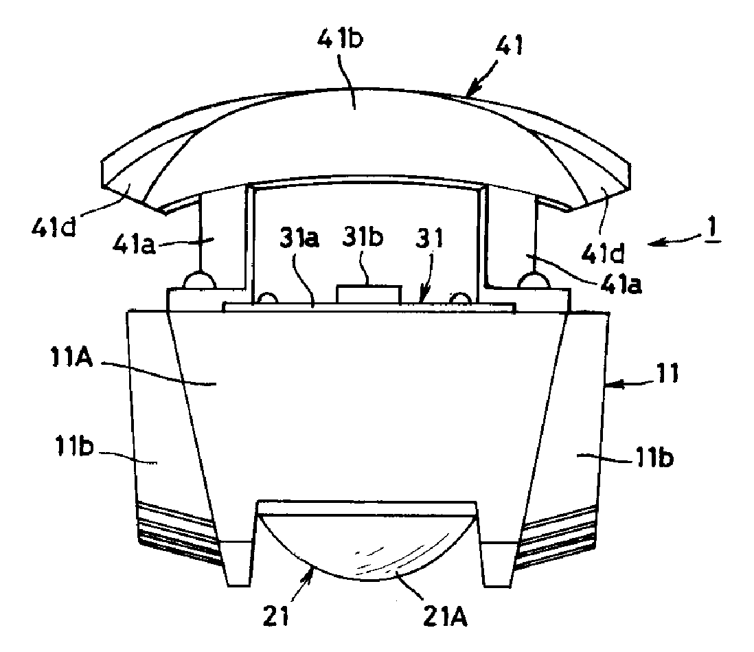
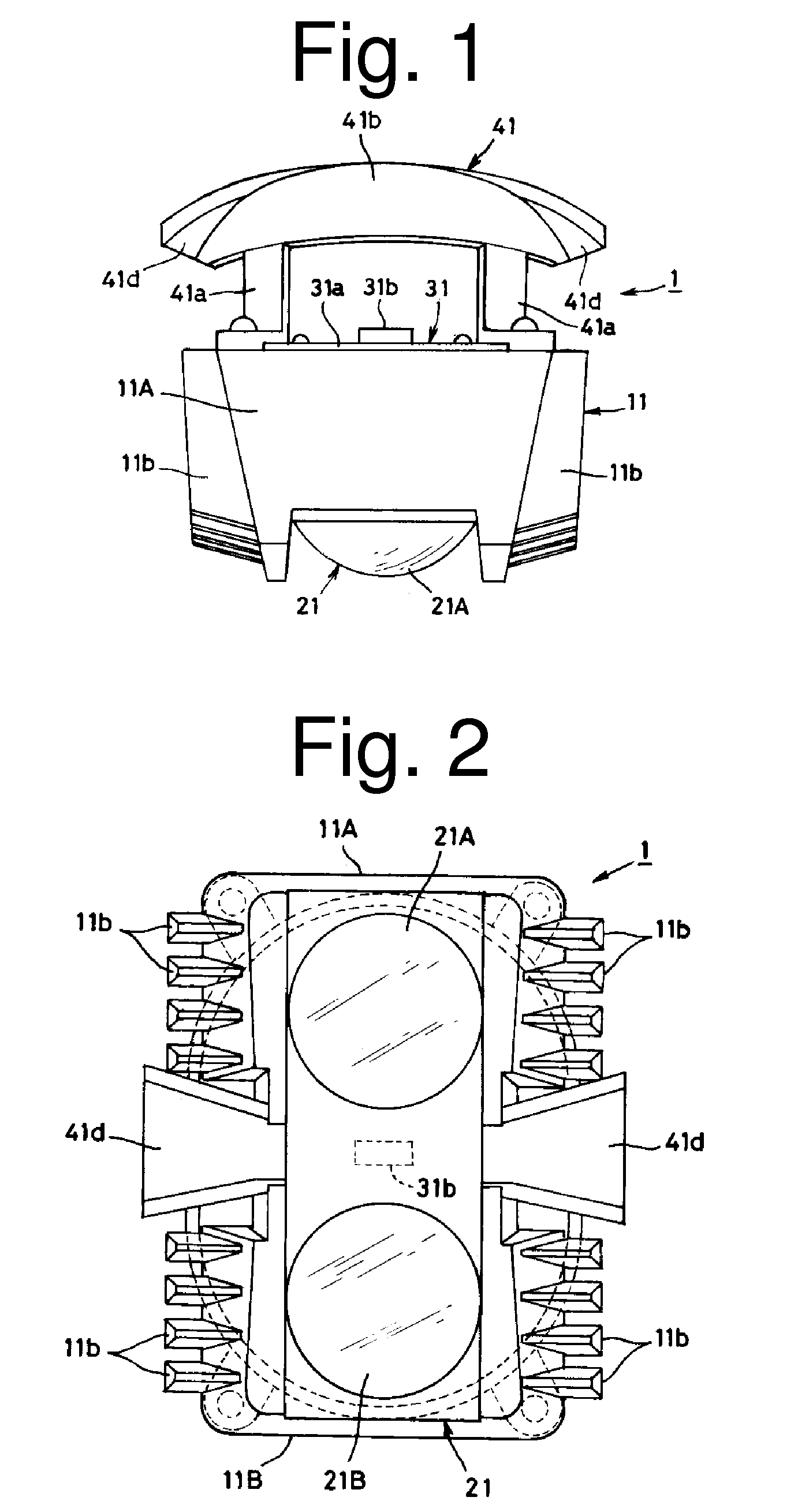
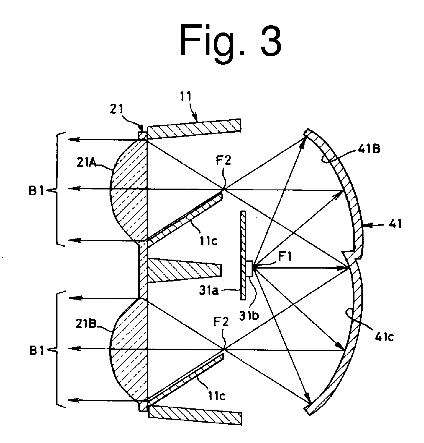
[0030]The first exemplary embodiment of the presently disclosed subject matter is a twin beam type vehicle light 1. FIG. 1 is a plan view of the vehicle light 1, FIG. 2 is a front view thereof, FIG. 3 is a schematic cross-sectional view thereof, and FIG. 4 is an exploded perspective view thereof. The vehicle light 1 can include a lens holder 11, a lens unit 21, a light source unit 31, and an elliptic reflector 41.

[0031]The lens holder 11 can be a main compon...


PUM


Abstract

A lighting device with a stable high light intensity can effectively dissipate heat generated by an LED so that the light emission efficiency does not deteriorate while the inside temperature distribution can be maintained in an even state. The lighting device can also be configured to prevent snow from adhering onto an outer lens by allowing an outer surface temperature of the lighting device to rise during actuation of the device. The lighting device can also be configured to improve light utilization efficiency. The lighting device can include a semiconductor light emitting device as a light source and can include structure(s) that guides the emission light to a projection lens. The semiconductor light emitting device can be configured to emit light in a reverse or opposed direction with respect to an illumination direction for the lighting device. A projection lens can be disposed in front of the semiconductor light emitting device. An elliptic reflector can be configured to reflect light from the semiconductor light emitting device and to direct the light to the projection lens. A lens holder can be made of metal and the semiconductor light emitting device and the projection lens can be disposed on the lens holder.

Description

[0001]This application claims the priority benefit under 35 U.S.C. §119 of Japanese Patent Application No. 2008-159308 filed on Jun. 18, 2008, which is hereby incorporated in its entirety by reference.TECHNICAL FIELD[0002]The presently disclosed subject matter relates to a lighting device including a semiconductor light emitting device (such as an LED) as a light source, and in particular, to a lighting device for use in a vehicle, that takes certain measures against heat generated by such a semiconductor light emitting device.BACKGROUND ART[0003]Conventional vehicle lights have employed a high intensity discharge lamp (HID lamp with approximately 3200 lm) and a halogen bulb (with 1000 to 1500 lm) as a light source. In order to reduce the power consumption and miniaturize the entire body size of the light, a projector type vehicle light that employs a semiconductor light emitting device as a light source is proposed in, for example, Japanese Patent Application Laid-Open No. 2003-317...

Claims


Application Information

Patent Timeline
Patent Type & Authority Applications(United States)
IPC IPC(8): F21V7/00F21V29/00
CPCF21S48/1159F21S48/328F21S48/335F21V7/0008F21V7/0025F21V13/12F21V29/90F21Y2101/02F21S48/137F21V29/713F21V29/763F21V29/89F21V29/004F21Y2115/10F21S41/29F21S41/336F21S45/60F21S45/48F21S41/145F21V29/70
Inventor FUTAMI, TAKASHI
Owner STANLEY ELECTRIC CO LTD
Why Eureka
Try Eureka