Thin film chemical analysis apparatus and analysis method using the same

a chemical analysis and thin film technology, applied in the direction of specific gravity measurement, laboratory glassware, instruments, etc., can solve the problems of liquid leakage out of the chamber, the inability to commercialize lab-on-chips, and the difficulty of making the analyzer thin film, etc., to achieve easy and fast detection of analyte, and long circulation and storage periods

Active Publication Date: 2009-12-24
PRECISIONBIOSENSOR INC
View PDF12 Cites 57 Cited by
  • Summary
  • Abstract
  • Description
  • Claims
  • Application Information

AI Technical Summary

Benefits of technology

[0222]The thin film chemical analysis apparatus and the analysis method using the same according to the present invention are suitable for a thin film-type apparatus for diagnosing and detecting a small amount of substance in a fluid, such as a lab-on-a-chip, a protein chip, or a DNA chip. Particularly, the inventive appar

Problems solved by technology

However, such a thin film-type analyzer has a problem in that the complicated design of valves for controlling the flow and flow rate of samples or reagents (enzymes and buffer solutions) renders it difficult to make the analyzer a thin film.
However, lab-on-a-chips cannot be commercialized until the following two problems are solved.
Firstly, the body of lab-on-a-chips repeats thermal expansion and contraction due to environmental factors (e.g. impact, temperature) during circulation and storage periods, even if the chambers are closed by physical valves.
As a result, the valves have minute gaps, through which the liquid leaks out of the chambers due to the capillary phenomenon.
Secondly, although the liquid-phase substance must be stored in the chambers stably for a long period of time, the liquid itself is subjected to pressure resulting from evaporation and convection when the lab-on-a-chips are exposed to

Method used


Image

  • Thin film chemical analysis apparatus and analysis method using the same
  • Thin film chemical analysis apparatus and analysis method using the same
  • Thin film chemical analysis apparatus and analysis method using the same

Examples


Embodiment Construction

[0251]Hereinafter, exemplary embodiments of the present invention will be described with reference to the accompanying drawings.

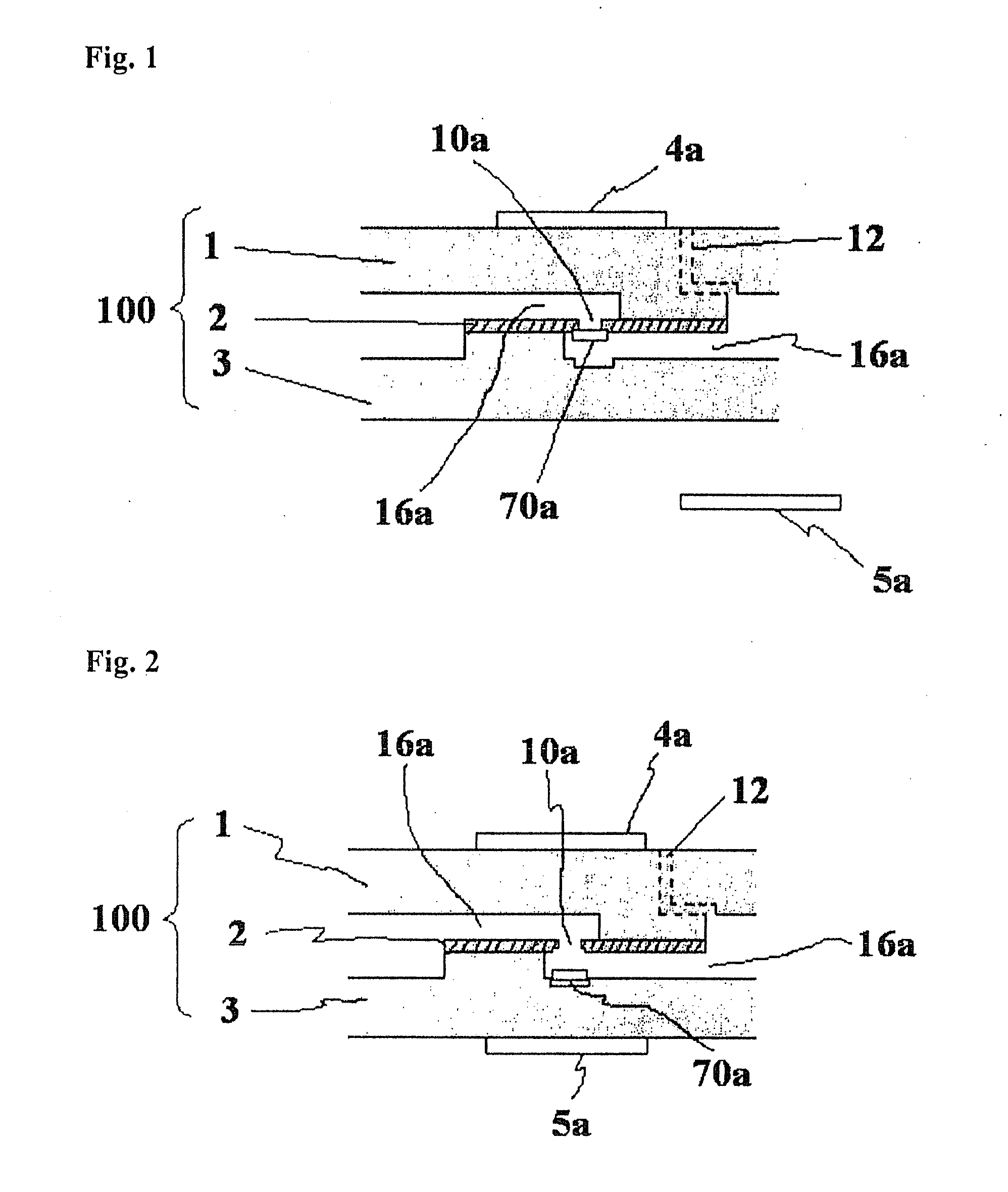
[0252]FIGS. 1 and 2 show a valve using a microbead installed inside the body of a thin film chemical analysis apparatus 100 according to an embodiment of the present invention, when the valve is opened and closed, respectively.

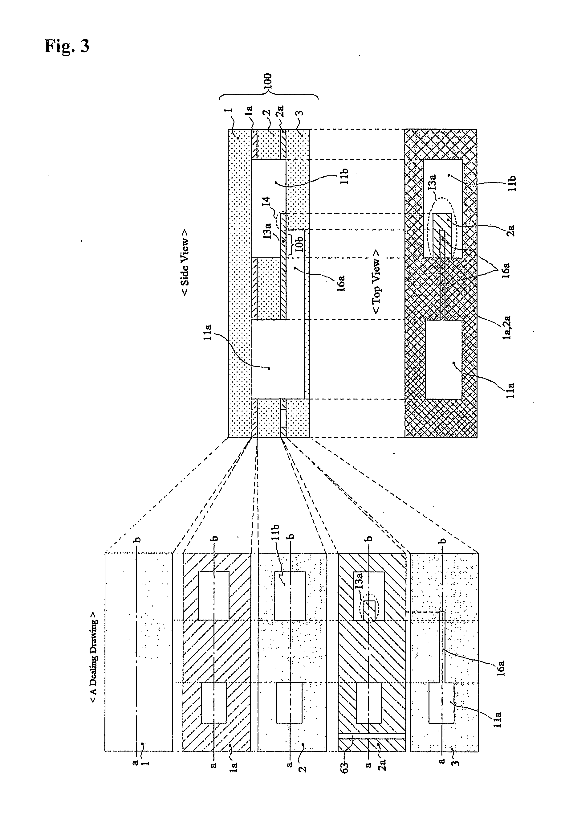
[0253]Referring to FIGS. 1 and 2, a thin film valve according to an embodiment of the present invention uses a thin film-type cylindrical permanent magnet.

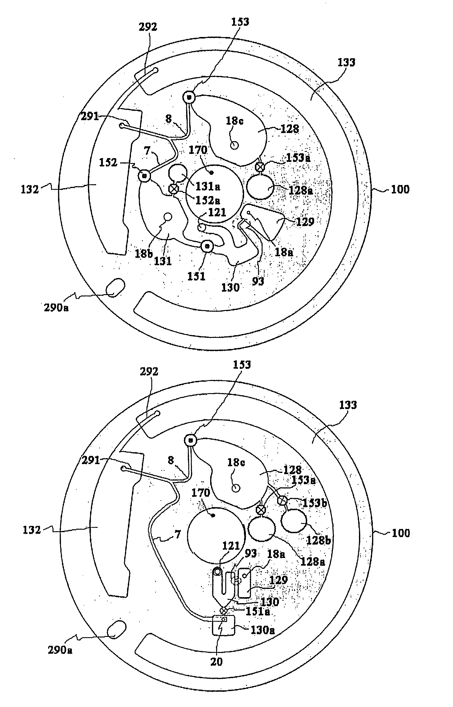
[0254]The body includes an upper substrate 1, a middle substrate 2, and a lower substrate 3, each of which forms a plurality of channels for enabling a fluid to flow on the substrate surface during an injection molding process, chambers for storing a buffer solution, and holes for interconnecting the channels. These components are fastened and attached to one another to constitute a thin film chemical analysis apparatus.

[0255]FIG. 1 corresponds to a case in which the thin film-type ...


PUM


Abstract

Disclosed is a thin film chemical analysis apparatus and an analysis method using the same, which can solve the sealing problem caused by environmental factors (e.g. impact, temperature) for long circulation and storage periods, as well as can detect an analyte quickly and easily. The thin film chemical analysis apparatus includes at least one chamber adapted to store a fluid necessary for biological or biochemical analysis or to conduct a biological or biochemical reaction; channels for fluid-connection of the chambers; holes arranged between or inside the channels and connected to the channels; a rotatable body having the chambers, the channels, and the holes integrated into the body; and a burst valve having a sealing means for closing the hole and sealing a fluid in the chamber, the sealing means being torn away from the hole by centrifugal force resulting from rotation of the body and opening the hole.

Description

TECHNICAL FIELD[0001]The present invention relates to a thin film chemical analysis apparatus and an analysis method using the same. More particularly, the present invention relates to a thin film chemical analysis apparatus adapted for a thin film-type apparatus for diagnosing and detecting a small amount of substance in a fluid, such as a lab-on-a-chip, a protein chip, or a DNA chip, and an analysis method using the same.BACKGROUND ART[0002]The present application is a continuation of Korean Patent Application No. 10-2001-0003956 (Jan. 27, 2001) entitled “NUCLEIC HYBRIDIZATION ASSAY METHOD AND DEVICE USING CLEAVAGE TECHNIQUE SPECIFICALLY RESPONSIVE TO SPECIFIC SEQUENCE OF COMPLEMENTARY DOUBLE BOND STRAND OF NUCLEIC ACID AND OLIGONUCLEOTIDE”; PCT Application No. PCT / KR02 / 00126 (Jan. 27, 2002) entitled “NUCLEIC HYBRIDIZATION ASSAY METHOD AND DEVICE USING A CLEAVAGE TECHNIQUE RESPONSIVE TO THE COMPLEMENTARY DOUBLE STRAND OR THE SINGLE STRAND OF NUCLEIC ACIDS OR OLIGONUCLEOTIDES”; Kor...

Claims


Application Information

Patent Timeline
IPC IPC(8): C12M1/34G01N33/00
CPCB01L3/502738F16K2099/0084B01L2200/16B01L2300/021B01L2300/022B01L2300/0806B01L2300/0867B01L2400/0409B01L2400/0633B01L2400/0677B01L2400/0683F16K99/0001F16K99/003F16K99/004F16K99/0057B01L2200/0689G01N33/48G01N33/50G01N35/02
Inventor YOO, JAE-CHERN
Owner PRECISIONBIOSENSOR INC
Why Eureka
Try Eureka