Rubber strip material

a technology of rubber strips and rubber strips, applied in the field of rubber strips, can solve the problems of reducing productivity, difficult to make the performance compatible with one another, and the function of the inner liner to cut the permeation of air may not be fulfilled, so as to reduce the number of windings and shorten the fabrication cycle time of the rubber member

Active Publication Date: 2009-12-31
TOYO TIRE & RUBBER CO LTD
View PDF5 Cites 26 Cited by
  • Summary
  • Abstract
  • Description
  • Claims
  • Application Information

AI Technical Summary

Benefits of technology

[0015]According to the rubber strip material of the invention, since the rubber strip material is made up of two or more types of rubber compounds and hence two or more types of rubber compounds can be wound in a single winding step, a rubber member made up of a combination of a plurality of rubber compounds can be formed with a reduced number of times of winding, and because of this, the fabrication cycle time of the rubber member can be shortened.

Problems solved by technology

However, due to a problem that a rubber strip member distorts or contracts by the rubber strip member being extruded and molded by the extruding machine and cut to a fixed dimension, as is disclosed in Patent Document No. 1 and Patent Document No. 2 below, a non-vulcanized rubber strip material which has been extruded and molded into a ribbon shape is wound in an overlapping fashion in a tire circumferential direction on a rotational support element such as a building drum to thereby form a rubber member having a predetermined cross sectional shape.
However, in the event that a certain degree of thickness is not imparted to the inner liner rubber portion 1, the thickness thereof becomes uneven due to rubber getting out of position during a vulcanization process, leading to a fear that the function of an inner liner to cut of the permeation of air may not be fulfilled.
These respective performances of low rolling resistance, wet performance and wear resistance tend to contradict to one another in view of rubber characteristics, and hence, it is difficult to make those performances compatible with one another.
When building the rubber members like the inner liner rubber portion 1, the tread rubber portion 2, and the side wall portion 3 which are each made up of a combination of a plurality of rubber compounds by winding spirally the aforesaid ribbon-shaped unvulcanized rubber strip material in an overlapping fashion, since the winding step needs to be implemented for each of the rubber compounds which make up the rubber member, there is caused a problem that the fabrication cycle time of each rubber member is lengthened to thereby reduce the productivity thereof.

Method used


Image

  • Rubber strip material
  • Rubber strip material
  • Rubber strip material

Examples


embodiment 1

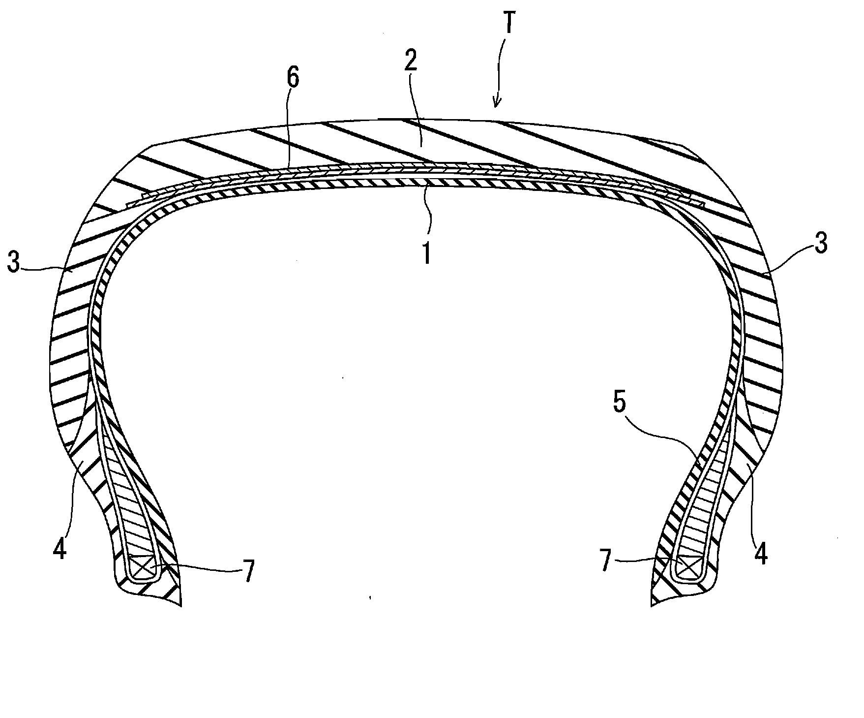
[0031]This embodiment is such that an inner liner rubber portion 1 is built by laminating two types of rubber materials having different air permeabilities, and for example, a lower layer 1a which is provided on an internal side of a tire as is shown in FIG. 6 is made of a rubber material having a low air permeability, and an upper layer 1b which is provided on an upper surface of the lower layer la is made of a hard rubber material which prevents the movement of the lower layer 1a during a vulcanization process.

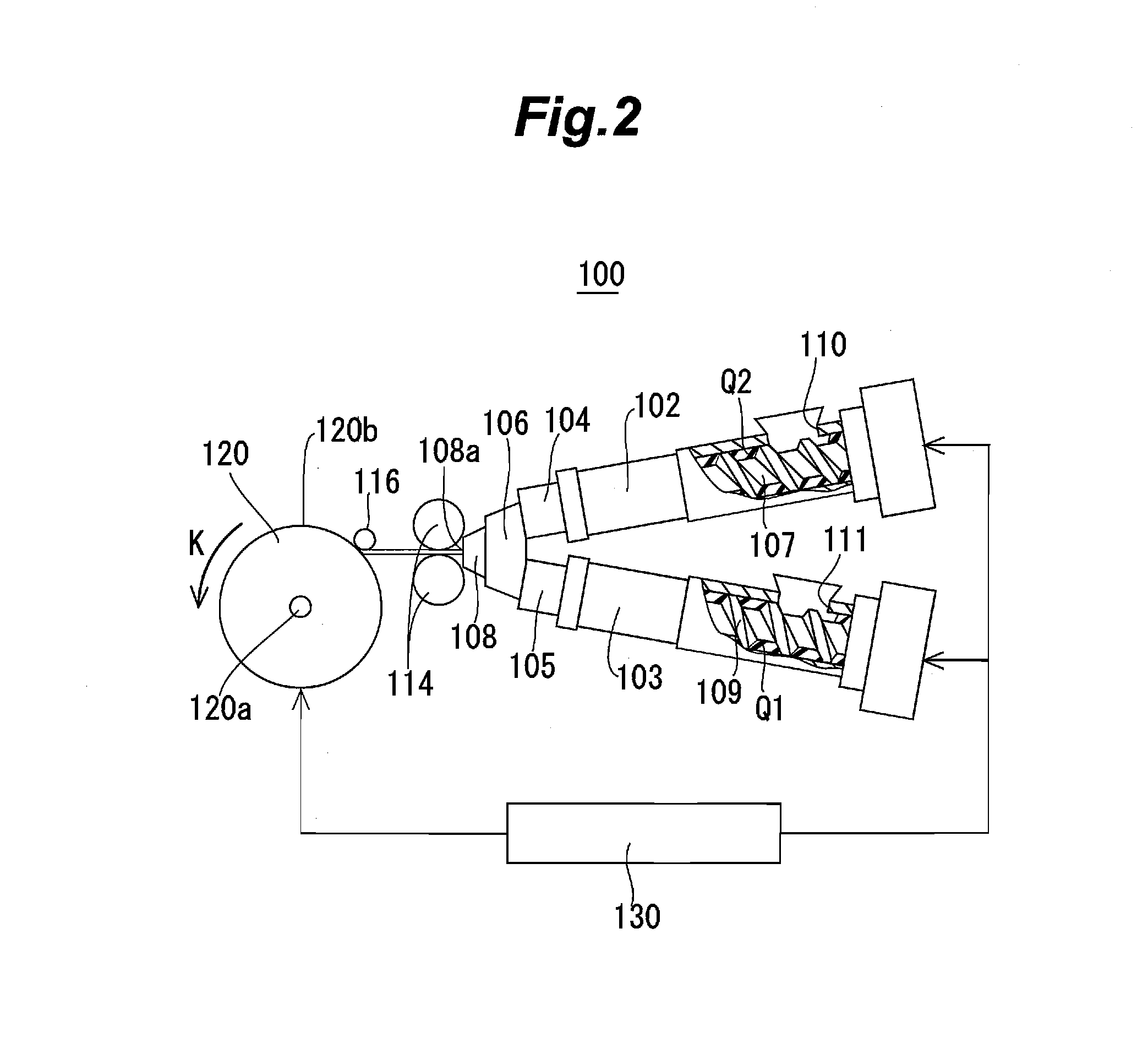
[0032]The inner liner rubber portion 1 which is configured as has been described above is built by feeding a rubber strip material 10a on to the rotational support element 120 for building a tire and winding spirally the rubber strip material 10a so fed on to the rotational support element 120 in the tire circumferential direction A in a partially overlapping fashion (refer to FIG. 2).

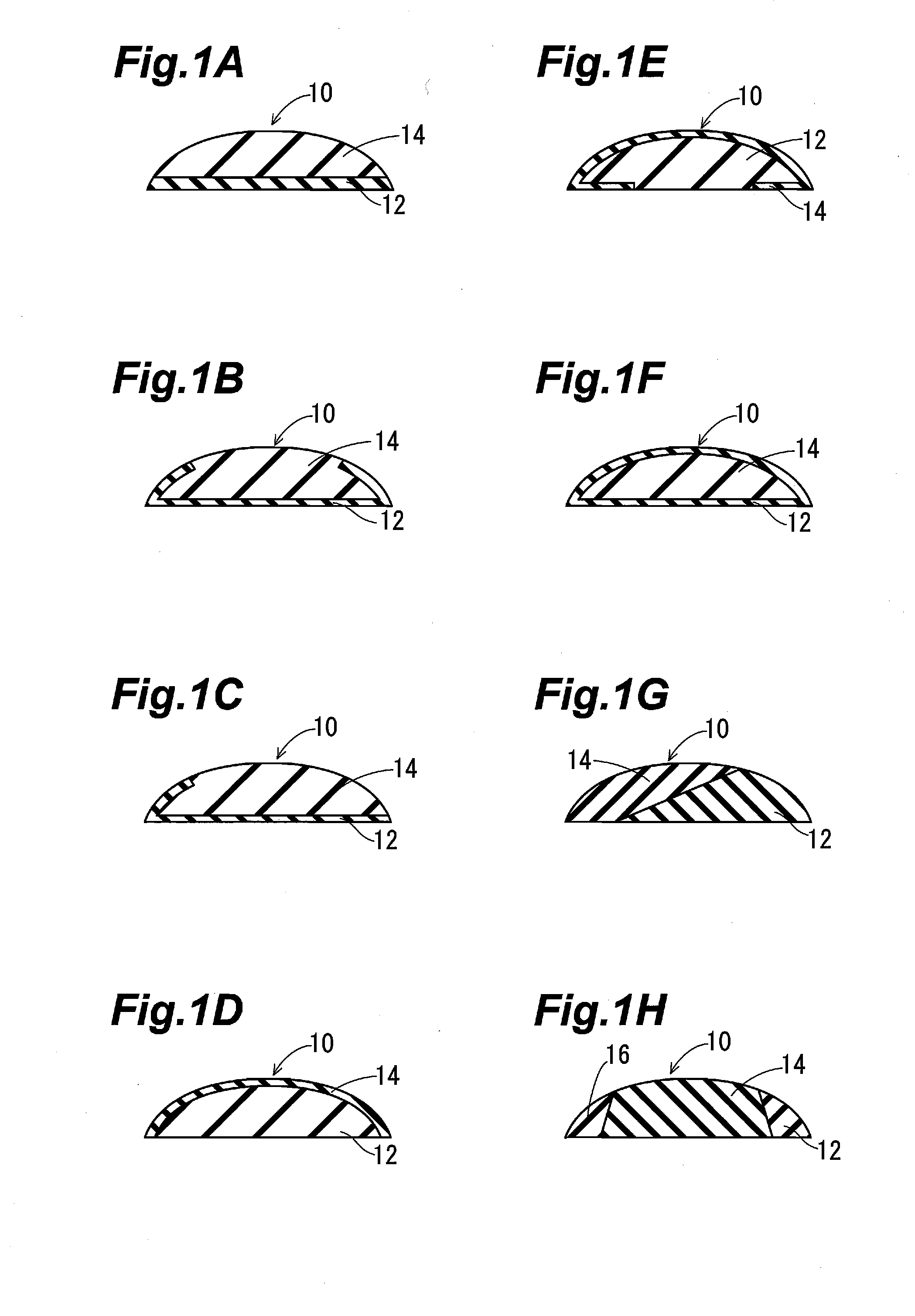
[0033]A cross section of the rubber strip material 10a is divided into a first region 12a w...

embodiment 2

[0039]This embodiment is such that a tread rubber portion 2 is built which is made by laminating three types of rubber compounds in a thickness direction, and for example, as is shown in FIG. 7, a lower layer 2a of a tread rubber portion 2 which contacts a belt layer 6 is made up of a rubber compound having a low rolling resistance, an intermediate layer 2b made up of a rubber compound having an increased wet performance is formed on an upper surface of the lower layer 2a, and a surface layer 2c made up of a rubber compound having an increased wear resistance is provided over a whole area of an upper surface of the intermediate layer 2b. A boundary 2d separating the lower layer 2a from the intermediate layer 2b is provided substantially parallel to a lower layer 2a side surface and a boundary 2e separating the intermediate layer 2b and the surface layer 2c is provided substantially parallel to a surface layer 2c side surface on which a recess is provided at a tire widthwise central ...

embodiment 3

[0058]This embodiment is such that a side wall portion 3 is built by laminating three types of rubber compounds in a thickness direction, and for example, as is shown in FIG. 8, a lower layer 3a which is made up of a first rubber compound which prevents the movement of a rubber material at the time of vulcanization is formed on an internal side of a side wall portion 3 which contacts a carcass layer 5 of a tire T, a surface layer 3c which is made up of a third rubber compound having a high degree of hardness is formed on a surface of a side wall portion 3, and an intermediate layer 3b which is made up of a second rubber compound with an increased manuevability is provided between the lower layer 3a and the surface layer 3c.

[0059]The side wall portion 3 configured as described above is built, as is shown in FIG. 14, by feeding a ribbon-shaped first rubber strip material 10g whose cross section is divided into a first region 12g which is made up of the first rubber compound which pre...


PUM


Abstract

When forming a rubber member which is made up of a combination of a plurality of rubber compounds by winding spirally a ribbon-shaped unvulcanized rubber strip material in an overlapping fashion, the number of times of winding is reduced so as to shorten a fabrication cycle time of the rubber member to thereby increase the productivity thereof. As a means therefore, a rubber strip material whose cross section is divided into two or more regions which are made up of different rubber compounds is wound spirally on to a drum in an overlapping fashion so as to build a green tire or a tire rubber member.

Description

TECHNICAL FIELD[0001]The present invention relates to rubber strip materials which are used for fabricating a green tire made up of a plurality of tire rubber members.BACKGROUND ART[0002]In general, tires are configured in such a manner as to include a plurality of tire rubber members and a plurality of reinforcement members which are mainly made up of cords. In a representative tire, as is shown in FIG. 5, respective portions such as an inner liner rubber portion 1, a tread rubber portion 2, side wall rubber portions 3, rim strip rubber portions 4 and the like are formed by rubber members which match properties required for the respective portions and these rubber members are combined with a carcass layer 5 which constitutes a cord-contained reinforcement member, a belt layer 6 and bead elements 7 to thereby make up a tire T1.[0003]To mold rubber members which make up the respective portions, rubber materials were extruded continuously to be molded into rubber strips from an extrud...

Claims


Application Information

Patent Timeline
Patent Type & Authority Applications(United States)
IPC IPC(8): B60C9/00
CPCB29D30/3028B29D30/60Y10T428/24504Y10T152/10783Y10T428/24479
Inventor KUDO, SHIGEOTATARA, TETSUOFUJIKI, OSAMUHITOTSUYANAGI, MITSURU
Owner TOYO TIRE & RUBBER CO LTD
Why Eureka
Try Eureka