Ion Transfer Tube with Spatially Alternating DC Fields

Active Publication Date: 2009-12-31
THERMO FISHER SCI BREMEN
View PDF7 Cites 47 Cited by
  • Summary
  • Abstract
  • Description
  • Claims
  • Application Information

AI Technical Summary

Benefits of technology

[0023]The foregoing ion transfer channel embodiment may be utilized in relatively high pressure regions of a mass spectrometer, wherein ion motion through the channel is dominated by and defined by the gas flow conditions. In many cases the flow through the channel is characterized by a substantially constant velocity for ions and molecules of all masses. Additional forces may arise from net (i.e. smoothed) DC gradients. Successful operation of the ion transfer channel will generally require that that mean free

Problems solved by technology

There is a significant loss in existing ion transfer arrangements, so that the majority of those ions generated by the ion source do not succeed in reaching and passing through the ion transfer arrangement into the subsequent stages of mass spectrometry.
This diminishes the number of ions delivered to the mass analyzer and adversely affects instrument sensitivity.
Furthermore, for tubes constructed of a dielectric material, collision of ions with the tube wall may result in charge accumulation and inhibit ion entry to and flow through the tube.
Unfortunately, effective operation of ion funnel extends only up to gas pressures of approximately 40 mbar, i.e 4% of atmospheric pressure.
However, it does not address the issue of focusing ions in the pres

Method used


Image

  • Ion Transfer Tube with Spatially Alternating DC Fields
  • Ion Transfer Tube with Spatially Alternating DC Fields
  • Ion Transfer Tube with Spatially Alternating DC Fields

Examples


Embodiment Construction

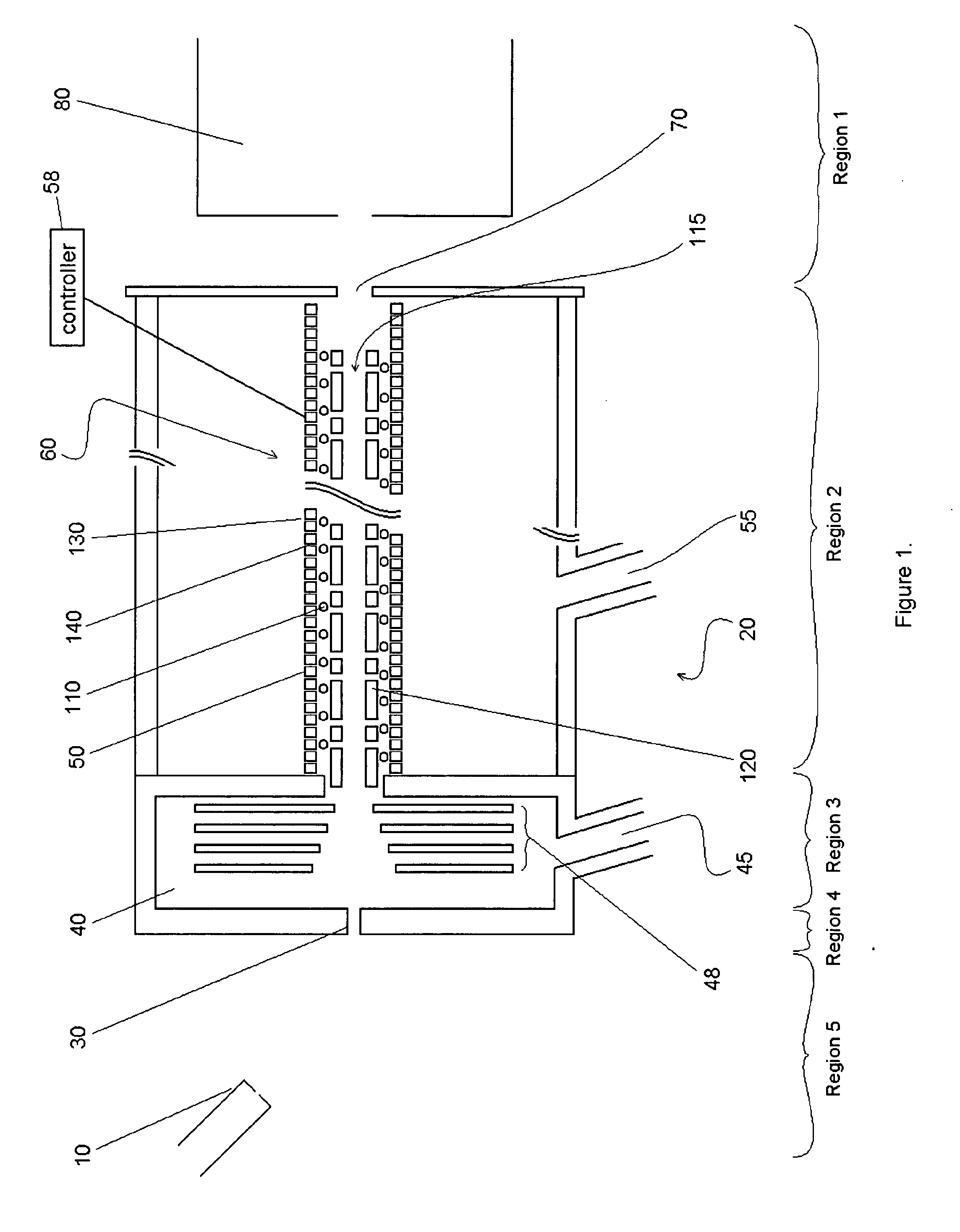
[0036]FIG. 1 shows an ion transfer arrangement embodying various aspects of the present invention, for carrying ions between an atmospheric pressure ion source (e.g. electrospray) and the high vacuum of a subsequent vacuum chamber in which one or more stages of mass spectrometry are situated. In FIG. 1, an ion source 10 such as (but not limited to) an electrospray source, atmospheric pressure chemical ionization (APCI) or atmospheric pressure photoionization (APPI) source is situated at atmospheric pressure. This produces ions in well known manner, and the ions enter an ion transfer arrangement (indicated generally at reference numeral 20) via entrance aperture 30. Ions then pass through a first pumped transport chamber 40 (hereinafter referred to as an expansion chamber 40) and on into a second vacuum chamber 50 containing an ion conduit 60. Ions exit the conduit 60 and pass through an exit aperture 70 of the ion transfer arrangement where they enter (via a series of ion lenses—not...


PUM


Abstract

An ion transfer arrangement for transporting ions between higher and lower pressure regions of a mass spectrometer includes an electrode assembly (120) with a first plurality of ring electrodes (205) arranged in alternating relation with a second plurality of ring electrodes (210). The first plurality of ring electrodes (205) are narrower than the second plurality of ring electrodes (210) in a longitudinal direction, but the first plurality of ring electrodes have a relatively high magnitude voltage of a first polarity applied to them whereas the second plurality of ring electrodes (210) have a relatively lower magnitude voltage applied to them, of opposing polarity to that applied to the first set of ring electrodes (205). In this manner, ions passing through the ion transfer arrangement experience spatially alternating asymmetric electric fields that tend to focus ions away from the inner surface of the channel wall and towards the channel plane or axis of symmetry.

Description

FIELD OF THE INVENTION[0001]This invention relates to an ion transfer arrangement, for transporting ions within a mass spectrometer, and more particularly to an ion transfer arrangement for transporting ions from an atmospheric pressure ionisation source to the high vacuum of a mass spectrometer vacuum chamber.BACKGROUND OF THE INVENTION[0002]Ion transfer tubes, also known as capillaries, are well known in the mass spectrometry art for the transport of ions between an ionization chamber maintained at or near atmospheric pressure and a second chamber maintained at reduced pressure. Generally described, an ion transfer channel typically takes the form of an elongated narrow tube (capillary) having an inlet end open to the ionization chamber and an outlet end open to the second chamber. Ions, together with charged and uncharged particles (e.g., partially desolvated droplets from an electrospray or APCI probe, or Ions and neutrals and Substrate / Matrix from a Laser Desorption or MALDI so...

Claims


Application Information

Patent Timeline
IPC IPC(8): H01J3/18H01J49/04
CPCH01J49/065
Inventor MAKAROV, ALEXANDERPESCH, REINHOLDROBERT, MALEKKOZLOVSKIY, VIACHESLAV
Owner THERMO FISHER SCI BREMEN
Why Eureka
Try Eureka