
Radar level gauging system with galvanically isolating communication link

a communication link and radar technology, applied in the field of radar level gauging system, can solve the problems of time-consuming and difficult system operation, complex system, and high cost, and achieve the effects of improving signal processing, improving usability, and improving system efficiency

Inactive Publication Date: 2009-12-31
ROSEMOUNT TANK RADAR
View PDF6 Cites 22 Cited by
  • Summary
  • Abstract
  • Description
  • Claims
  • Application Information

AI Technical Summary

Benefits of technology

The present invention provides an improved sensor system for determining the level of a surface of a product in a tank. The system includes a propagation device and at least two radar level gauge (RLG) units. The RLG units communicate with each other through a communication link that ensures galvanic isolation between the units. The system also includes an isolating interface that prevents any conductive connection between the RLG units. The RLG units can communicate various control data, such as configuration data or measurement data, without compromising their independent functionality. The control data can be entered manually or received through a data input device. The communication link can be based on optical signals or wireless network technology. The technical effects of the invention include simplified sensor system configuration, improved signal processing, and increased usability and efficiency of the sensor system.

Problems solved by technology

In systems with several independent sensors of this or similar type, the independency requirements make the system complex and expensive.
In addition, operation of the system becomes time consuming and difficult, as large amounts of data must be communicated to each sensor.

Method used


Image

  • Radar level gauging system with galvanically isolating communication link
  • Radar level gauging system with galvanically isolating communication link
  • Radar level gauging system with galvanically isolating communication link

Examples


Embodiment Construction

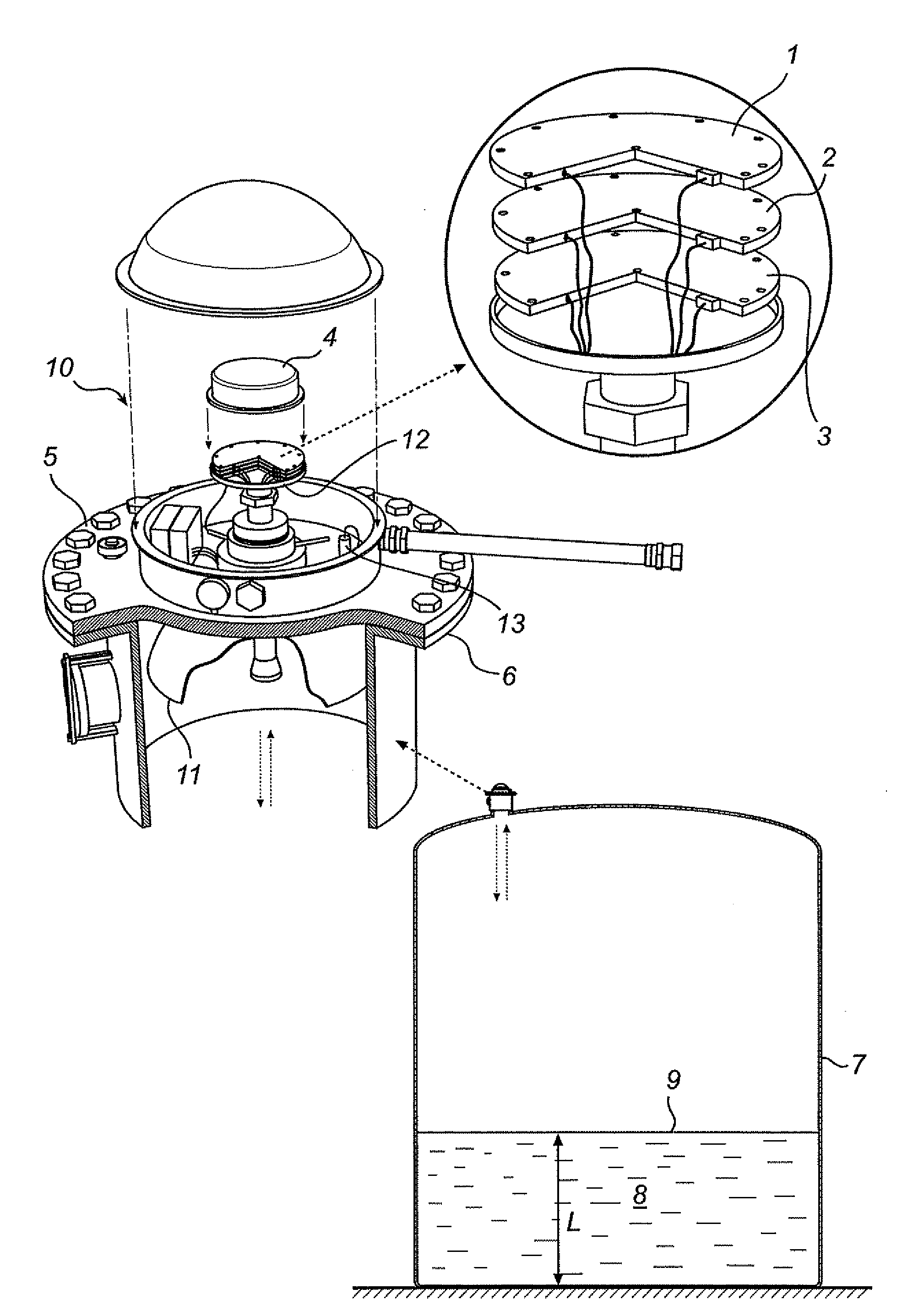
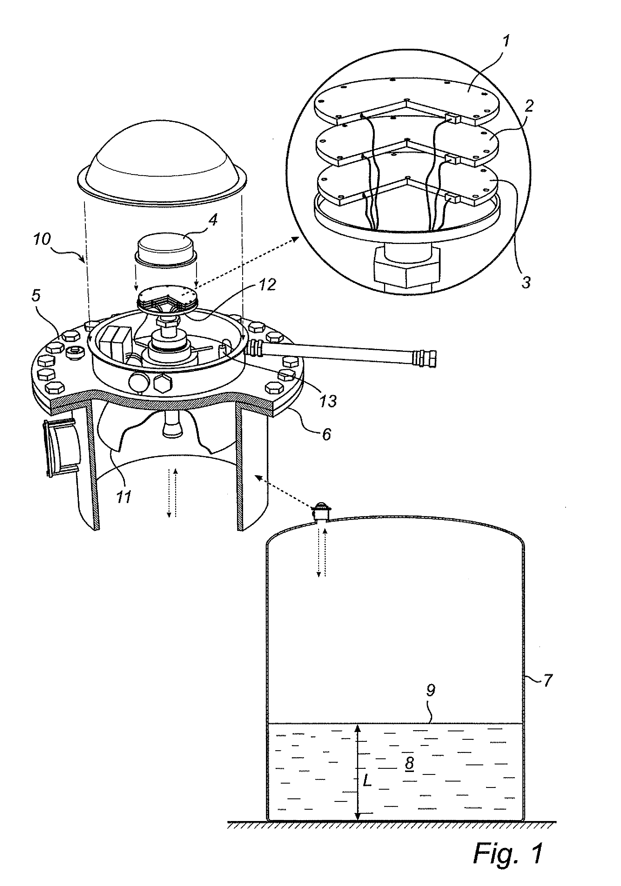
[0024]The invention will be described with reference to a radar level gauging system 10 in FIG. 1, having three radar level gauge (RLG) units 1, 2, 3 physically integrated inside a protective housing 4. The housing 4 here comprises an outer cover 4a, as well as an inner cover 4b. At least the outer cover is adapted to protect the electronics in the gauging system from the outside environment, such as sea water spray if the system is mounted on a tank ship. At least one of the covers 4a, 4b may further be conductive, so as to shield the electronics from electromagnetic disturbance.

[0025]The system 10 has a flange 5 that is mounted on a corresponding flange 6 of an opening in the roof of a tank 7. The tank may be a stationary process tank as indicated in FIG. 1, but may also be a tank on a moving vessel, such as a tank ship. Each RLG unit is arranged to perform measurements of a process variable such as the filling level L or ullage level of a product 8 contained in the tank 7, by tra...


PUM


Abstract

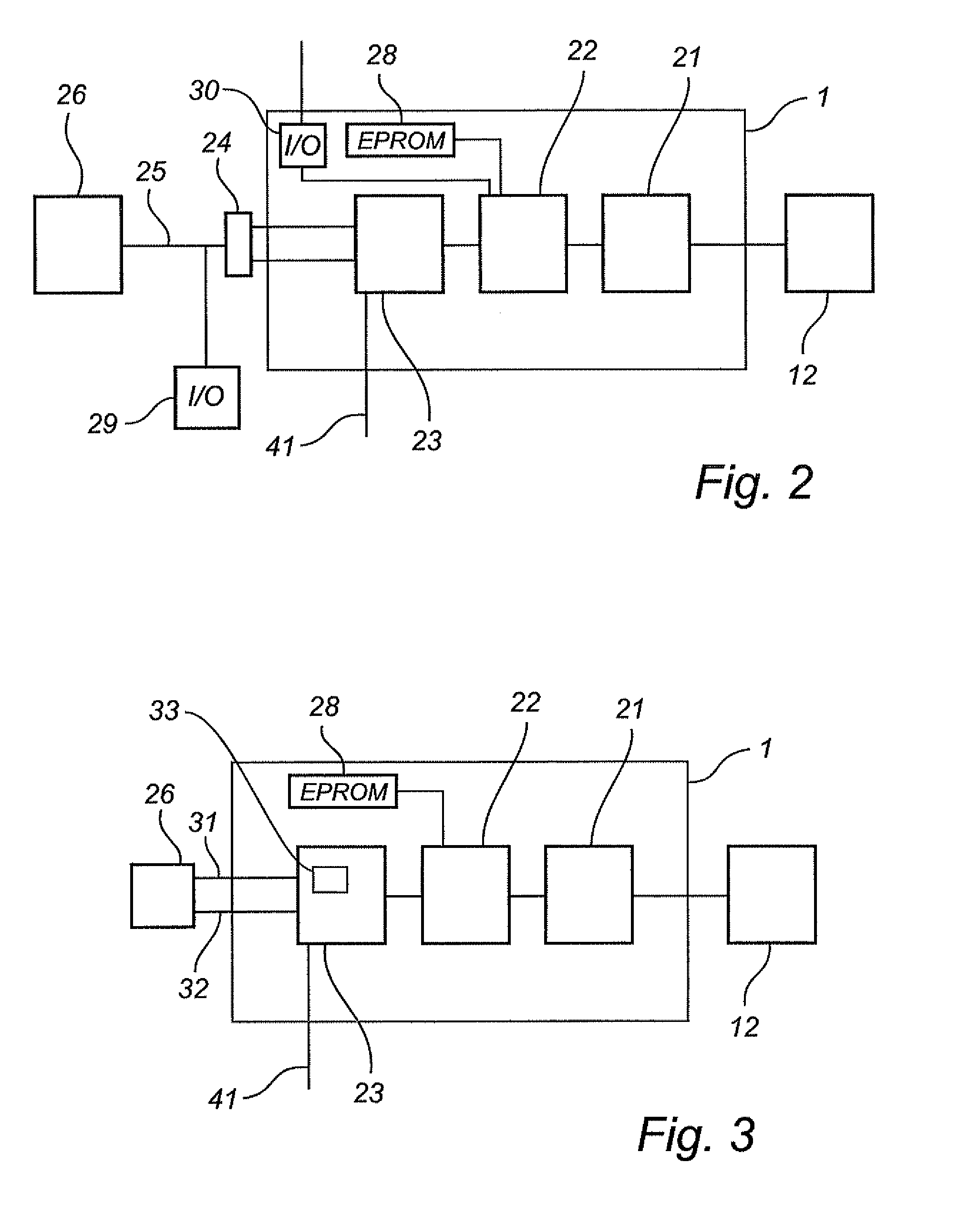
A radar level gauging system for determining a level of a surface of a product in a tank, comprising a propagation device arranged to allow microwave signals to propagate towards the surface, and to return a reflection of the microwave signals from the surface and at least two radar level gauge (RLG) units. Each RLG unit includes transceiver circuitry, processing circuitry connected to the transceiver circuitry and adapted to determine the level based on a relation between transmitted and received signals, and a communication interface. The system further comprises a communication link interconnecting the RLG units, for communicating control data between the RLG units, the communication link comprising an isolating interface, ensuring galvanic isolation between the RLG units.One unit may hereby communicate configuration data to the rest of the RLG units which results in a simplified configuration of the sensor system and thus more cost effective compared to the prior art solutions.

Description

FIELD OF THE INVENTION [0001]The present invention relates to a radar level gauging system for measuring process variables in a tank, and in particular the exchange of control data in such a system.TECHNICAL BACKGROUND [0002]Radar level gauging systems can be arranged in a tank, in order to provide information about process variables of a product in the tank. Examples of process variables that may be determined by such sensors are filling level, product composition, inflow, etc.[0003]In such gauging systems, function independence is sometimes required. For example, safety regulations require that a high level alarm sensor and / or an overfill alarm sensor function independently of a level measurement sensor as well as of each other. Functional independence here means that a fault in one system does not render the other system(s) inoperative.[0004]Such independence can be achieved by having several RLG units galvanically isolated from each other. This results in a system where each RLG...

Claims


Application Information

Patent Timeline
Patent Type & Authority Applications(United States)
IPC IPC(8): G01S13/08
CPCG01F23/284G01S7/03G01S13/88G01S13/87G01S13/34G01F25/20
Inventor HALL, OLAWELIN, ANDERS
Owner ROSEMOUNT TANK RADAR
Learn More