Optical characterisation methods and systems

a technology of optical characterisation and optical characterisation, applied in the field of optical characterisation of fluids, can solve the problems of limited amount of fluid material typically available for characterisation, air-liquid surface, measurement disturbance, etc., and achieve the effect of large dynamic range in which optical characterisation can be performed and limited evaporation

Inactive Publication Date: 2009-12-31
TRINEAN
View PDF16 Cites 16 Cited by
  • Summary
  • Abstract
  • Description
  • Claims
  • Application Information

AI Technical Summary

Benefits of technology

[0005]It is an object of the present invention to provide good devices for assisting in optical characterization of fluids and good apparatus and methods for optically characterizing fluids. It is an advantage of particular embodiments of the present invention that small amounts of fluids can be studied, e.g. drops or droplets such as fluids with a volume down to 1 μl, even down to 1 nanoliter. It is also an advantage of particular embodiments of the present invention that the dynamic range in which optical characterization can be performed is large, i.e. that fluids within a wide range of absorption coefficients can be measured. It is an advantage of particular embodiments of the present invention that optical characterization can be performed without contaminating the illumination or detection unit. It is furthermore an advantage of particular embodiments of the present invention that dynamic measurements are performed, i.e. during the filling of the measurement reservoir, as this results in an automated way of coping with different absorption coefficients of the fluids to be characterized. It is also an advantage of particular embodiments of the present invention that the devices, apparatus and methods can be used for different types of optical characterization, such as e.g. photometry, spectrophotometry, fluorometry or spectrofluorometry. It is also an advantage that the gates to the measurement volume or to a predetermined part thereof may be small, e.g. minimised, such that only a small area of the fluid surface is exposed to air and thus the evaporation is limited.

Problems solved by technology

In a large number of today's applications, the amount of fluid material typically available for performing characterisation is limited.
The technique typically requires direct contact between the sample and the read-out unit, implying that the measurement may be disturbed by contaminations originating from previous measurements.
Furthermore, due to the lack of a suitable containing structure around the sample fluid, the free air-liquid surface is large and therefore evaporation of the liquid sample can occur on a short time scale.
However, filling of small reservoirs with liquids and control thereof is difficult due to the need for pressure to introduce the fluid in the small reservoir.

Method used


Image

  • Optical characterisation methods and systems
  • Optical characterisation methods and systems
  • Optical characterisation methods and systems

Examples


first embodiment

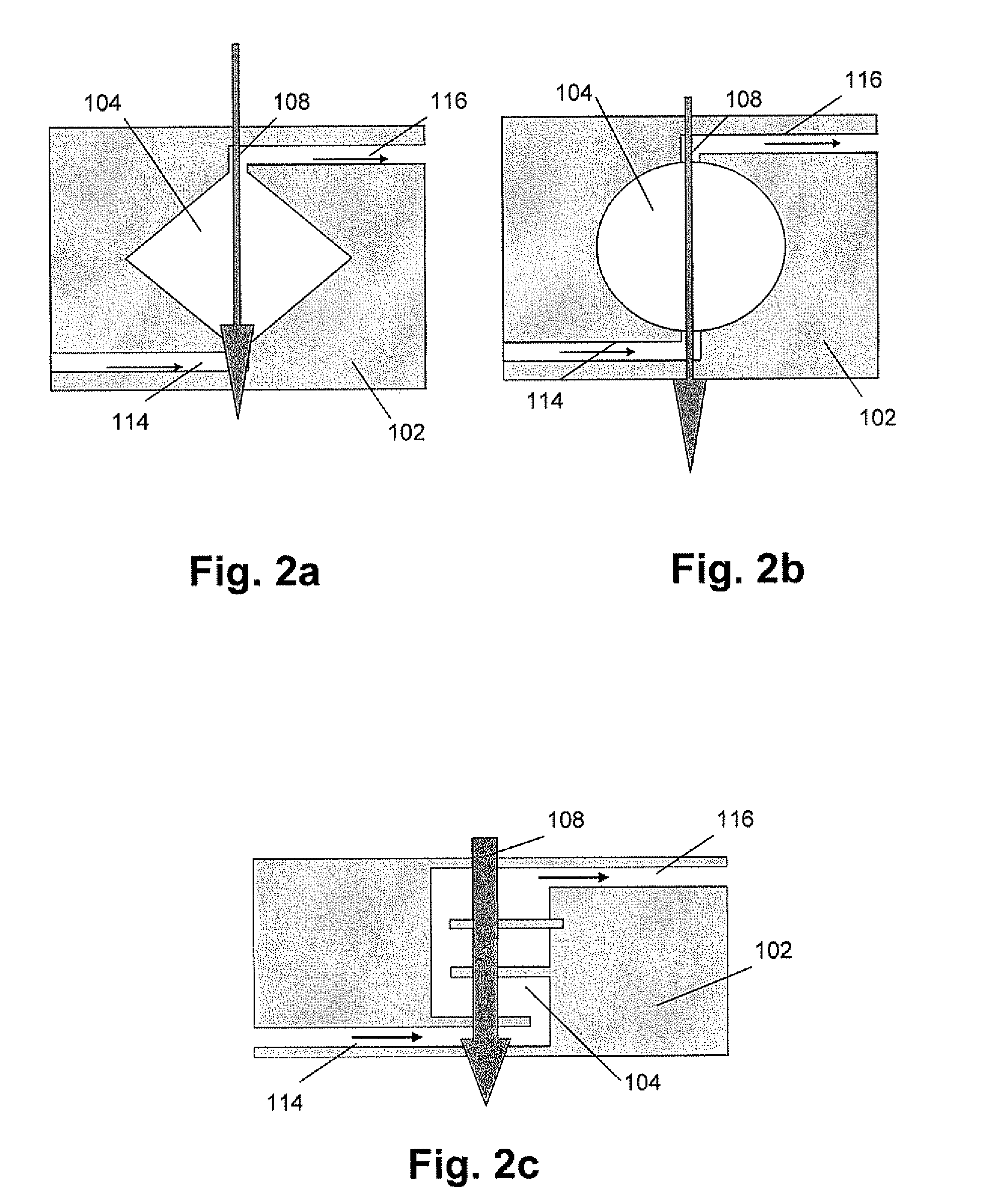
[0135]In a first embodiment according to the first aspect, the present invention relates to a device for assisting in optical characterisation of a fluid as described above, comprising the same advantages as described above, wherein the measurement reservoir comprises a measurement reservoir shape such that different cross-sections in a direction perpendicular to the filling direction are present and wherein a large interaction path of the probing beam with the fluid sample is present. The latter is obtained by a measurement reservoir shape wherein each of the cross-sections is adapted for crossing the optical path of an illumination beam used for characterising a fluid. The high overlap with the illumination beam may, for example, be suitable for sample fluids with a small amount of analytes to be detected, as the higher possibility to interact with the sample fluid may lead to an increased detection level. An example of such a structure is illustrated in FIG. 5a, whereas the resul...

second embodiment

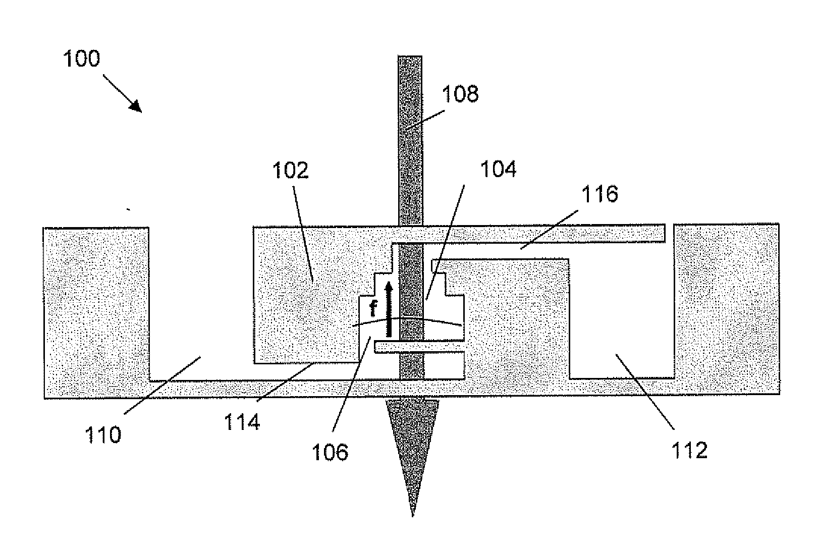
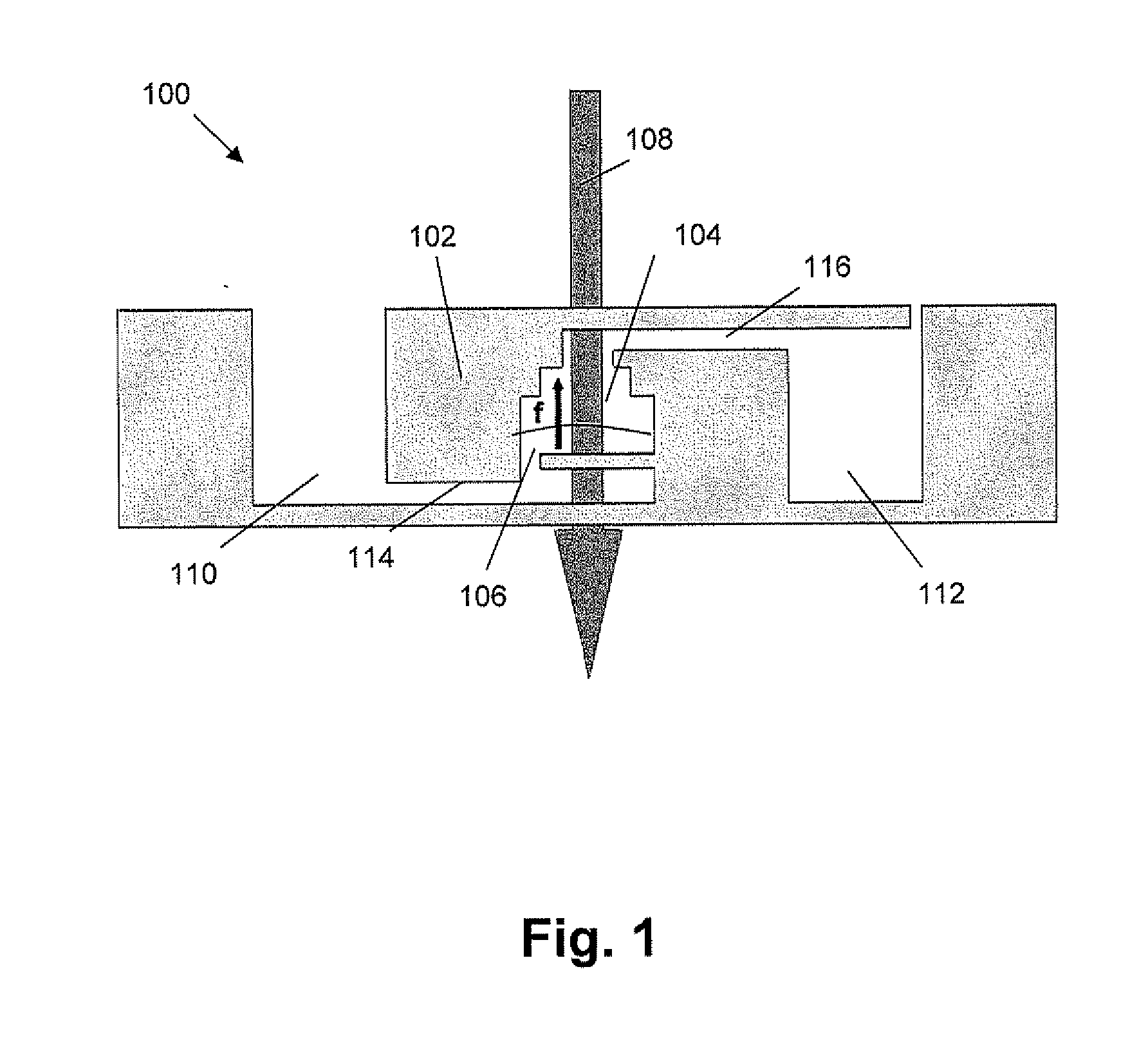
[0137]In a second embodiment according to the first aspect, the present invention relates to a device for assisting in optical characterisation of a fluid as described above, wherein the measurement reservoir comprises a measurement reservoir shape such that at least one cross-section of the measurement reservoir in the direction perpendicular to the filling direction does not cross the illumination path. In other words, there may be an intermediate cross-section of the measurement reservoir in the direction perpendicular to the filling direction, that is not in the optical path of the illumination beam. An example of such a structure is illustrated in FIG. 5c and FIG. 5e, whereas the resulting optical detection signal for a stepwise filled measurement reservoir 104 for a measurement reservoir shape as described in FIG. 5c is shown in FIG. 5d. For the ease, the following example is explained for a fixed filling rate. The device 100 comprises at least one measurement reservoir 104 co...

third embodiment

[0140]In a third embodiment according to the first aspect, the present invention relates to a device for assisting in optical characterisation of a fluid as described above, comprising the same advantages as described above, wherein different parts of the measurement reservoir surfaces have different properties for interacting with sample fluid. Typically these properties are the hydrophilic / hydrophobic properties of the surfaces. An example is shown in FIG. 6a. Variations of the filling pressure or input volumetric flow not caused by the measurement reservoir may be applied when using a device according to the present embodiment, as long as they are known such that they can be taken in to account for interpreting the obtained results. For the ease of explanation, the example is explained for a fixed filling pressure, although the invention is not limited thereto. The device 100 comprises at least one measurement reservoir 104 having in one part of the measurement reservoir, referre...


PUM

PropertyMeasurementUnit
diameteraaaaaaaaaa
volumeaaaaaaaaaa
volumeaaaaaaaaaa

Abstract

A device (100) for assisting in optical characterisation of a sample fluid. The device can comprise a substrate (102) with at least one measurement reservoir (104) adapted for filling with the fluid (106) in a filling direction. The device (100) thereby is adapted for receiving an illumination beam (108) for illuminating the fluid (106) in the at least one measurement reservoir (104). The at least one measurement reservoir is adapted for varying the rate of change of an optical path length of the illumination beam in the fluid. The measurement reservoir properties are adapted for providing information of an optical path length of the illumination beam in the fluid at a plurality of moments during the filling with the fluid. Furthermore a corresponding optical characterisation device is described. The invention also relates to a corresponding method.

Description

TECHNICAL FIELD OF THE INVENTION[0001]The present invention relates to the field of optical characterisation of fluids. More particularly, the present invention relates to components suitable for optical characterisation systems and optical characterisation systems and methods, such as e.g. for optical detection of biological, bio-chemical and / or chemical analytes in fluids.BACKGROUND OF THE INVENTION[0002]Optical characterisation techniques are frequently used for characterising materials, such as e.g. in material characterisation, medical applications, molecular diagnostics, chemical characterisation, etc. The latter typically may be used for characterising molecules, cells or small particles in small liquid samples, based on the measurement of light absorption and / or fluorescence in the sample. Besides the physical characteristics of the sample, the obtained optical signal typically also depends on the optical path length of the illumination beam in the liquid sample. The latter ...

Claims


Application Information

Patent Timeline
Patent Type & Authority Applications(United States)
IPC IPC(8): G01N21/11G01N21/00
CPCG01N21/05G01N2021/0346G01N2021/6482G01N21/532
Inventor NAESSENS, KRISBOCKSTAELE, RONNYLUYSSAERT, BERTBAETS, ROELAND
Owner TRINEAN
Why Eureka
Try Eureka