Wheel support bearing assembly equipped with sensor

a technology of wheel support bearings and sensors, which is applied in the direction of instruments, force/torque/work measurement apparatuses, transportation and packaging, etc., can solve the problems of strain in the sensor unit, and achieve the effects of improving assemblability, simplifying external devices, and facilitating mechanical vehicle control

Active Publication Date: 2009-12-31
NTN CORP
View PDF48 Cites 21 Cited by
  • Summary
  • Abstract
  • Description
  • Claims
  • Application Information

AI Technical Summary

Benefits of technology

[0022]When the external force acting on the wheel support bearing assembly or the working force acting between the tire and the road surface, which is obtained by the acting force estimation section, is utilized in vehicle control of the automotive vehicle, a meticulous vehicle control can be achieved. Since the signal transmitting path from the sensor signal processing circuit to the external device is employed in the form of a cable and the use is made of a connector for physically bonding and electrically connecting between the sensor signal processing circuit and the cable, the labor incurred in making a wired connection between the sensor signal processing circuit and the external device can be simplified and the assemblability can also be increased.
[0023]In the present invention, the signal transmitting path from the sensor signal processing circuit or t

Problems solved by technology

In the event that a load acts on the rotatable member as the automotive vehicle starts traveling, the stationary member undergoes

Method used


Image

  • Wheel support bearing assembly equipped with sensor
  • Wheel support bearing assembly equipped with sensor
  • Wheel support bearing assembly equipped with sensor

Examples


first embodiment

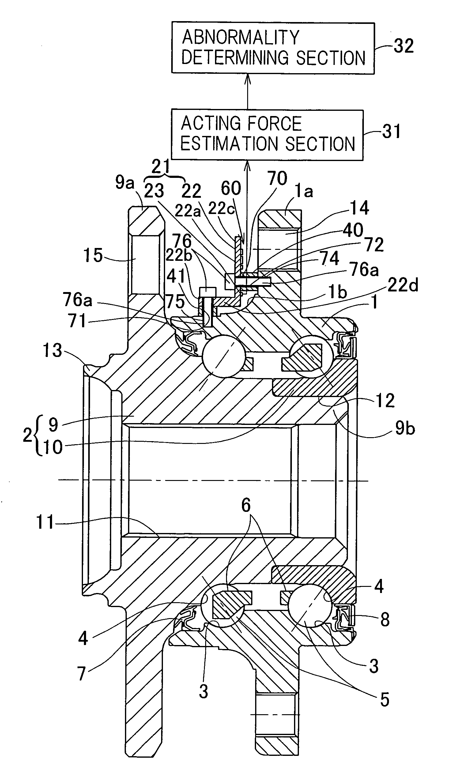
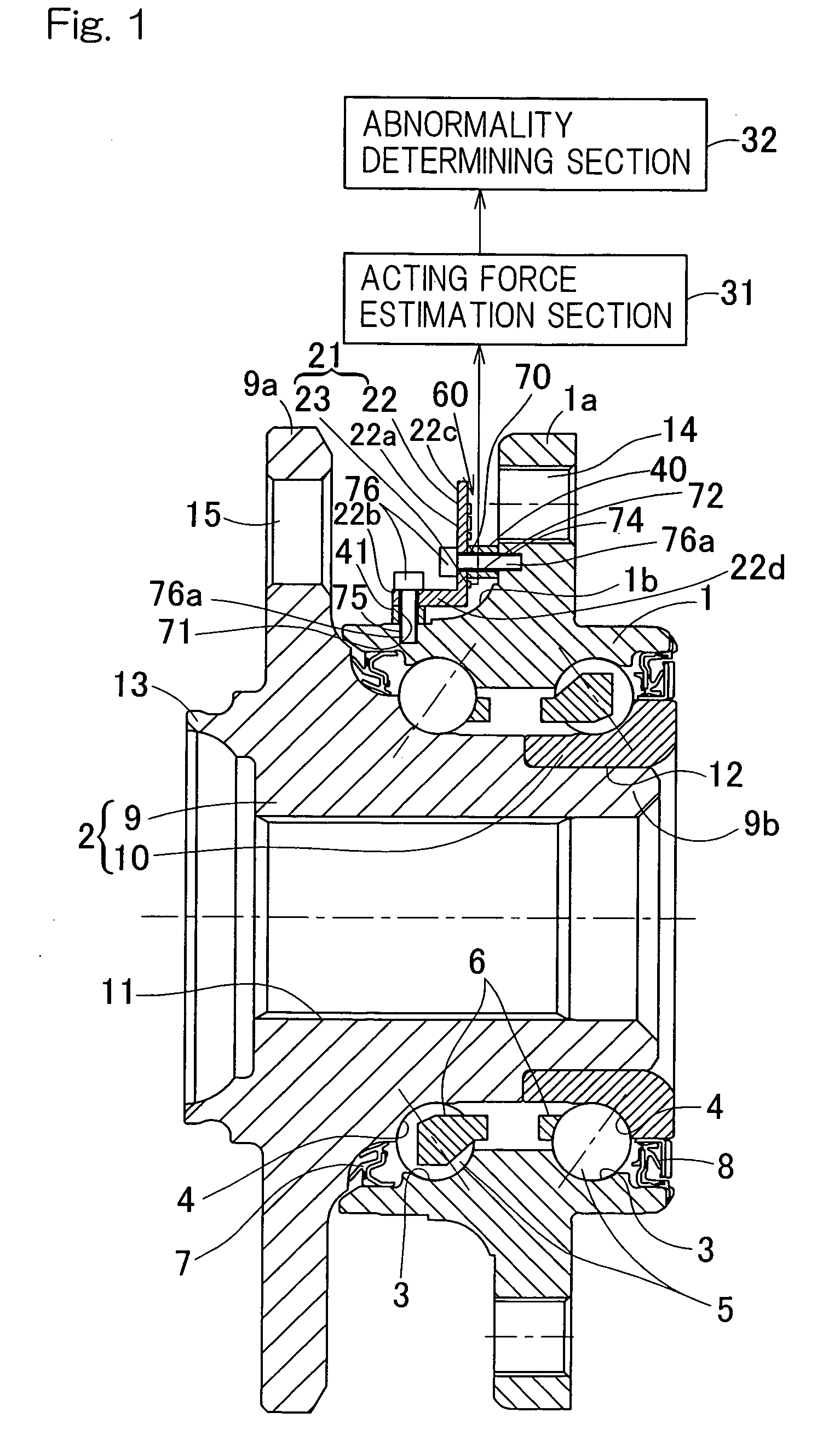
[0072]Also, since the sensor unit 21 is fitted to the outer member 1 through the first and second fixing members 40 and 41, not directly to the outer member 1, the sensor mounting member 22 can have a simplified L-shaped configuration. When the sensor mounting member 22 is of such a simplified shape, the sensor mounting member 22 can easily be processed and the production cost thereof can be reduced. Also, when the sensor mounting member 22 is of such a simplified shape, respective position at which the strain sensor 23 and the sensor signal processing circuit 60 are fixed can be precisely set. In the case of this first embodiment, since the sensor mounting surface 22A of the sensor mounting member 22, on which the strain sensor 23 is provided, is flat, it is easy to form the strain sensor 23 on the surface of the sensor mounting member 22 in the form of a thick film resistor.

[0073]Where the strain sensor 23 is structured by a metallic foil strain gauge, the strain sensor 23 is gene...

third embodiment

[0082]FIG. 9 corresponding to FIG. 6 illustrates the sensor unit employed in the sensor equipped wheel support bearing assembly according to a sixth preferred embodiment of the present invention. The sensor unit 21 shown therein is such that in a manner similar to that according to the previously described third embodiment shown in FIG. 6, the strain sensor 23 is fitted to the sensor mounting surface 22A of the sensor mounting member radially extending portion 22c and the sensor signal processing circuit substrate 61 is fitted to the surface 22B opposite to the sensor mounting surface 22A. The electrode 51 of the sensor mounting surface 22A and the electrode 65 of the opposite surface 22B are electrically connected with each other through a pin 67 inserted so as to extend through the radially extending portion 22c. By so constructing, even in the case where it is difficult to form the strain sensor 23 and the sensor signal processing circuit substrate 61 on one of the plural surface...

ninth embodiment

[0087]A ninth preferred embodiment of the present invention will now be described in detail with particular reference to FIGS. 14A and 14B. FIGS. 14A and 14B illustrate a sensor unit employed in the sensor equipped wheel support bearing assembly according to this ninth embodiment of the present invention, in which FIG. 14A is a fragmentary rear sectional view of the sensor unit and FIG. 14B is a side sectional view thereof. This illustrated sensor unit 21 includes a sensor mounting member 22, a strain sensor 23 for measuring a strain occurring in the sensor mounting member 22 and a sensor signal processing circuit substrate 61 on which a sensor signal processing circuit for processing an output from the strain sensor 23 are provided. The strain sensor 23 is formed on the sensor mounting surface 22A of the sensor mounting member 22 in the form of a thick film resistor in a manner similar to that described in connection with any one of the previously described embodiments.

[0088]The se...


PUM


Abstract

In a wheel support bearing assembly including double row rolling elements (3) between an outer member (1) and an inner member (2), a sensor unit (21) is fitted to one of the outer and inner members (1) and (2), which serves as a stationary member. The sensor unit (21) is made up of a sensor mounting member (22) and at least one or more strain sensor (23) fitted to the sensor mounting member (22). A sensor signal processing circuit (60) for processing an output signal from the strain sensor (23) is provided in the sensor mounting member (22).

Description

BACKGROUND OF THE INVENTION[0001]1. Field of the Invention[0002]The present invention relates to a sensor equipped wheel support bearing assembly having a load sensor built therein for detecting a load imposed on a bearing unit rotatably supporting a vehicle wheel.[0003]2. Description of the Prior Art[0004]For safety travel of an automotive vehicle, the wheel support bearing assembly equipped with a sensor for detecting the rotational speed of each of vehicle wheels has hitherto been well known in the art. While the automobile traveling safety precaution is generally taken by detecting the rotational speed of the respective vehicle wheel in various locations, it is not sufficient with only the rotational speed of the vehicle wheel and, therefore, it is desired to achieve a control for safety purpose with the use of other sensor signals.[0005]In view of the above, it may be contemplated to achieve the vehicle attitude control based on a load acting on each of the wheels during travel...

Claims


Application Information

Patent Timeline
IPC IPC(8): F16C32/00
CPCB60B27/0005B60B27/0068B60B27/0094F16C19/522G01L5/0019F16C2326/02F16C19/186
Inventor OZAKI, TAKAYOSHIISHIKAWA, TOMOMINISHIKAWA, KANTAROU
Owner NTN CORP
Why Eureka
Try Eureka