Fibers and methods relating thereto

a technology of fibers and fibers, applied in the field of fiber technology and nanotechnology, can solve the problems that the process did not attract the attention of researchers

Inactive Publication Date: 2009-12-31
BOARD OF RGT THE UNIV OF TEXAS SYST
View PDF86 Cites 51 Cited by
  • Summary
  • Abstract
  • Description
  • Claims
  • Application Information

AI Technical Summary

Benefits of technology

[0006]The proposed disclosure involves the production of polymer micro- and nanofibers optionally reinforced with nanoparticles. In one respect, fibers of the present invention incorporate carbon nanoparticles or inorganic nanoparticles into polymers that may render stronger and lighter fibers for various applications such as, but not limited to, tissue scaffolds, supports for enzymes and catalysts, filters, textiles, military or other clothing, electronic devices, optical devices, sensors, biosensors and reinforced composites. Micro- and nanofibers made of polymers without nanoparticles are also described herein.

Problems solved by technology

However, the process did not attract the attention of researchers until recently, as evidenced by the exponential increase in publications from less than 10 in 1994 to more than 250 in 2003.

Method used


Image

  • Fibers and methods relating thereto
  • Fibers and methods relating thereto
  • Fibers and methods relating thereto

Examples


example 1

Materials and Methods

Electrospinning

[0077]Polymer fibers were injected using a 10 mL glass syringe with an 18 needle gauge (1.23 mm OD×0.83 mm ID (internal diameter)), a 22 needle gauge (0.7 mm OD×0.4 mm ID), or a 26 needle gauge (0.45 mm OD×0.1 mm ID) at a flow rate of about 0.05 mL / min as controlled using a KDS 210 pump (KD Scientific Holliston Inc., MA). One of ordinary skill in the art can recognize that the needle gauge may vary depending on the desired diameter and may range from 8-34 gauge. A high power supply, ES30P-5W (Gamma High Voltage Research, Ormond Beach, Fla.) was also used. The equipment was coupled to the needle tip through an alligator clip and a voltage difference of between 5-50 kV, and in particular, 15 kV was used, and the grounded target was placed at 24.5 cm from the needle tip, although distances from between 5 to 50 centimeters may also be used.

Scanning Electron Microscopy (SEM)

[0078]For SEM analyses, a Leo 435 VP (Leo Electron Microscopy Ltd) was used to ...

example 2

Electrospun PMMA Nanofibers

[0081]Polymer samples were prepared by dissolving 7.5 wt. % PMMA in a 1:1 THF:DMF solvent mixture. PMMA (350,000 g / mol; Alfa Aesar); THF and DMF (Sigma-Aldrich), used without further purification.

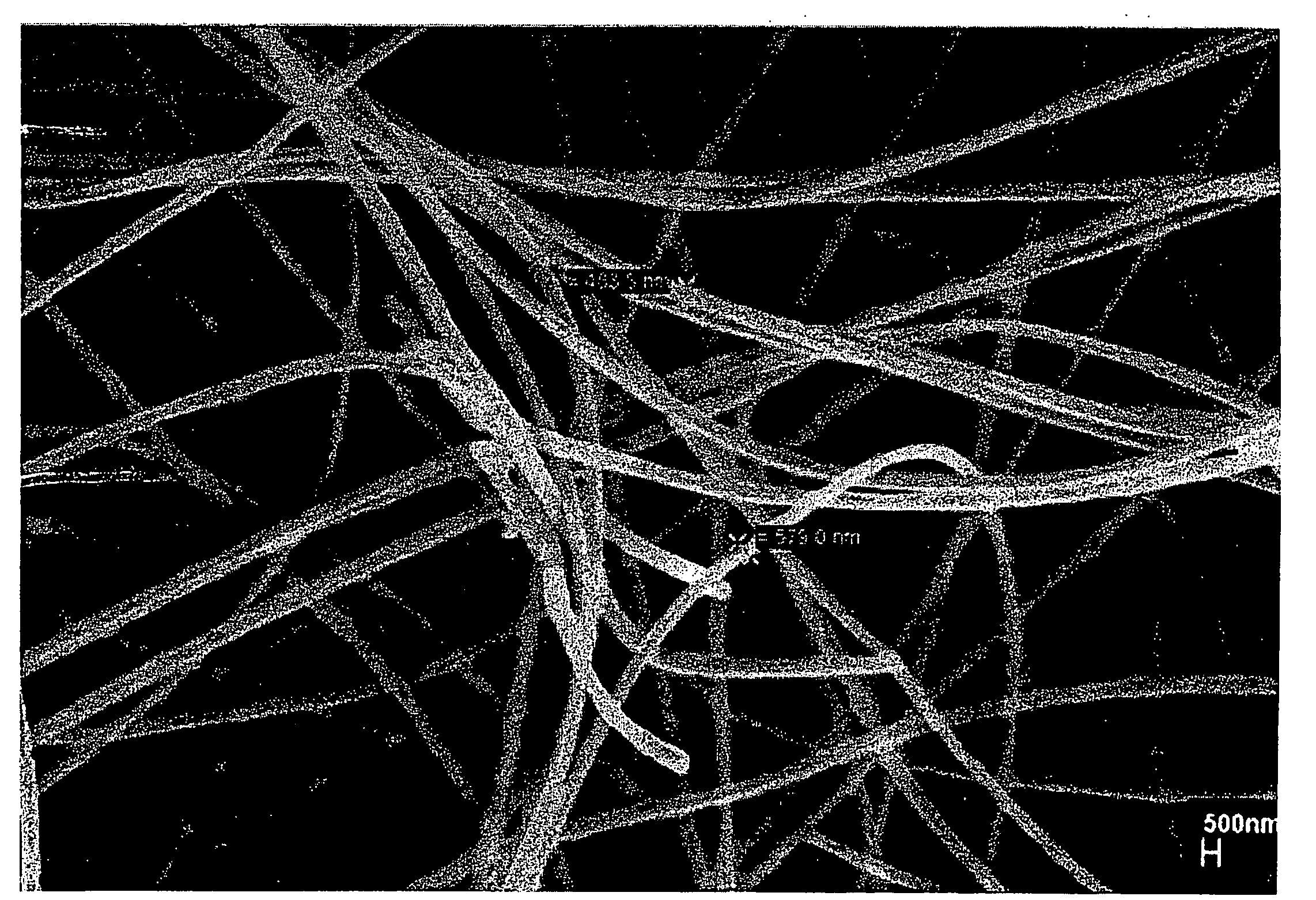
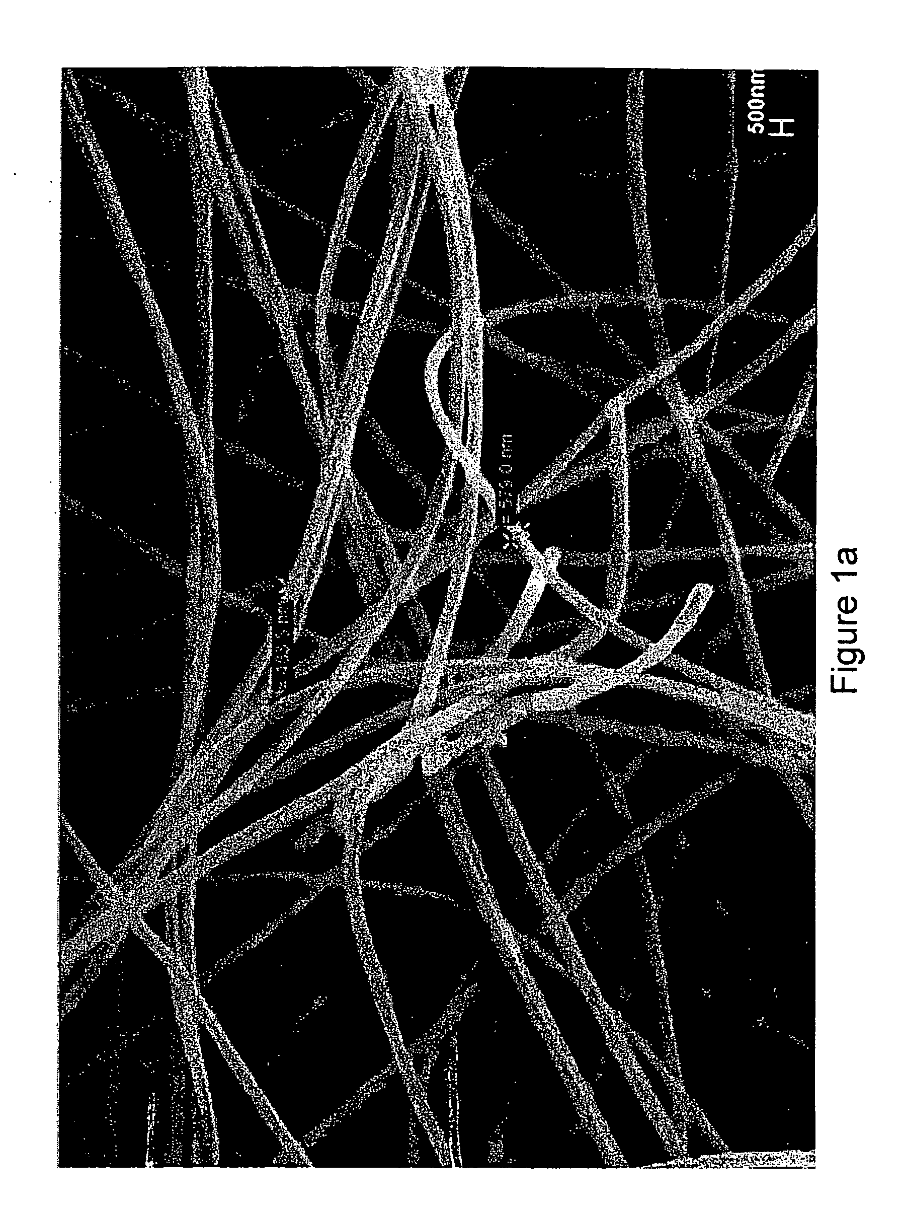
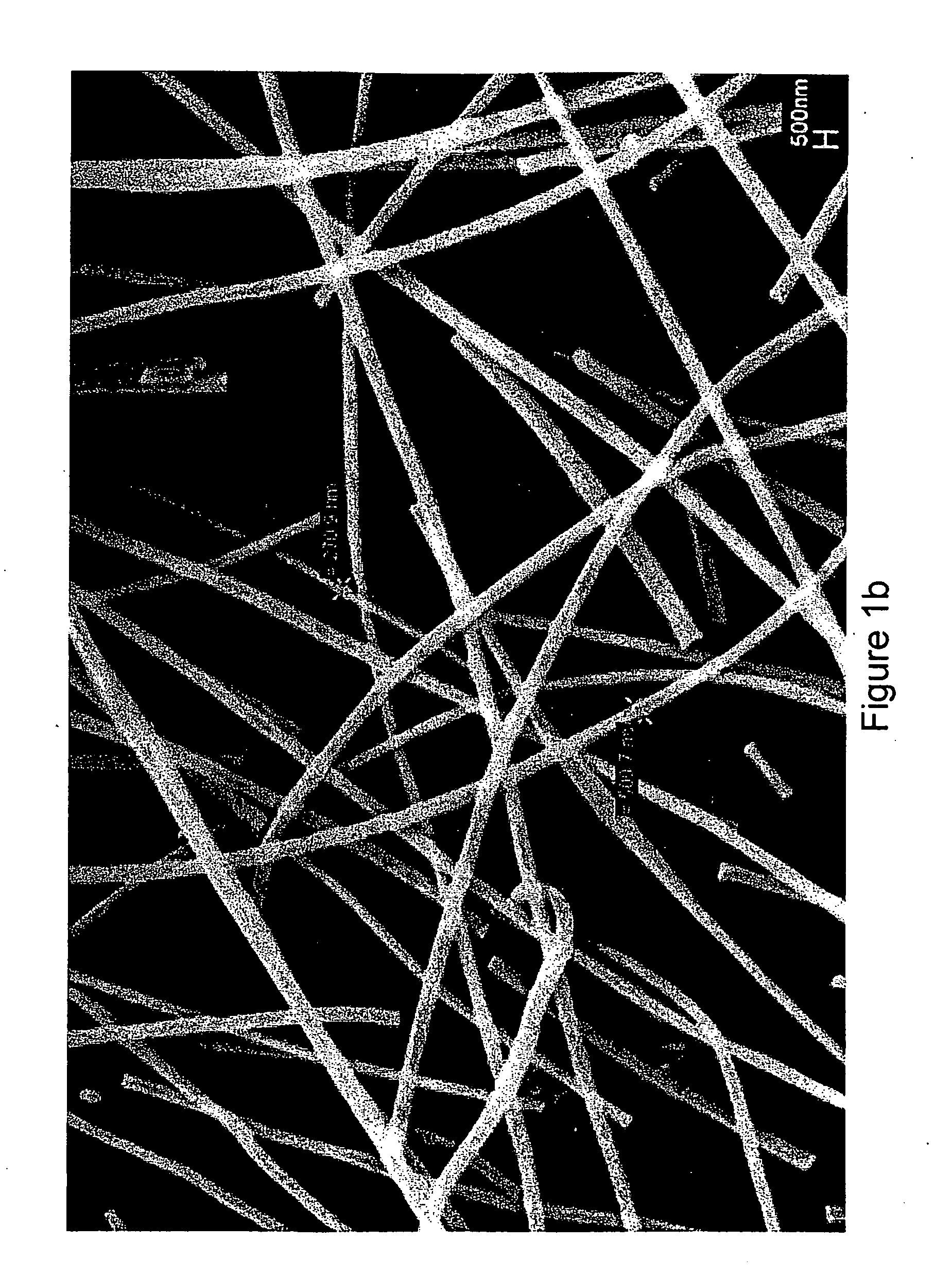
[0082]SEM micrographs of PMMA nanofibers obtained with needles with different internal diameters are presented in FIG. 1A-C. These fibers presented regular surface morphologies with a few nanofiber bundles being evident in FIGS. 1A-C. The resulting PMMA non-woven mats were analyzed (10-12 individual nanofiber diameters were measured) to calculate the average nanofiber diameter and standard deviation.

[0083]The thermogravimetric analysis (TGA) of PMMA samples in powder form and nanofibers are shown in FIG. 2, presenting all the samples a one step decomposition process. The TGA indicated an unexpected increase of about 40° C. in the onset decomposition temperature of PMMA from the powder form (about 266° C.) to the nanofiber (about 306° C.). Reports on TGA for polyme...

example 3

CNF-Reinforced Micro- and Nanofibers

[0086]PMMA (7.5%, 350,000 g / mol; Alfa Aesar) was dissolved in 1:1 THF / DMF. Next, 0.02 wt. % CNFs (vapor grown carbon nanofibers (Pyrograph III™) PR-24-RAW with diameters of 50-200 nm supplied by Applied Sciences, Inc. and purified according to the procedure reported by Lozano and collaborators (Lozano et al., 1999) were added and the solution was stirred vigorously for 20 hours.

[0087]In a separate experiment, 1.0 wt. % CHP was added to 7.5% PMMA in 1:1 THF / DMF, followed by addition of 0.002 wt. % CNFs. Vigorous stirring took place for 20 hours.

[0088]To avoid any nanoparticle sedimentation, each of these samples were then formed into micro- or nanofibers through the use of electrospinning as described above. Results may be seen in FIGS. 4 (SEM pictures) and 5 (TEM pictures).


PUM

PropertyMeasurementUnit
diameteraaaaaaaaaa
diameteraaaaaaaaaa
diameteraaaaaaaaaa

Abstract

The present invention provides micro- and nanofibers made from polymers that comprise nanoparticles, such as carbon nanoparticles and inorganic nanoparticles, and methods of making such fibers.

Description

RELATED U.S. APPLICATION DATA[0001]This application claims priority to U.S. Patent Application Ser. No. 60 / 916,605, filed on May 8, 2007, which is hereby incorporated by reference in its entirety.BACKGROUND OF THE INVENTION[0002]I. Field of the Invention[0003]The present invention relates generally to fiber technology, nanotechnology and, more particularly, to systems and methods for fabricating micro- and nanofibers and nanoparticle reinforced micro- and nanofibers.[0004]II. Description of Related Art[0005]Formhals described the process of electrospinning in several U.S. patents in the 1930's and 1940's to produce cellulose acetate, cellulose propionate and wool-cellulose acetate fibers. However, the process did not attract the attention of researchers until recently, as evidenced by the exponential increase in publications from less than 10 in 1994 to more than 250 in 2003. The driving force for the renewed interest in this technique is the possibility to produce inorganic and pol...

Claims


Application Information

Patent Timeline
Patent Type & Authority Applications(United States)
IPC IPC(8): C08K3/10C08G18/00C08G73/10C08F120/18C08F114/06C08G77/26C08L75/04C08L77/00C08L33/12C08L27/06D01D5/00
CPCB82Y30/00C08G77/458C08L33/12C08L2203/12D01F6/70D01F1/10D01F6/10D01F6/16D01F6/60D01D5/0038
Inventor MACOSSAY-TORRES, JAVIER
Owner BOARD OF RGT THE UNIV OF TEXAS SYST
Why Eureka
Try Eureka