Coil assembly for rotating electric machine

a technology of rotating electric machines and coils, which is applied in the direction of magnetic bodies, manufacturing stators/rotor bodies, and magnetic circuit shapes/forms/construction, etc., can solve the problems of reduced rigidity of half-coil conductors, reduced magnetic flux level or output of rotating electric machines, and reduced lamination factor of conductors, etc., to achieve a higher degree of freedom of layout, reduce the effect of bending

Inactive Publication Date: 2010-01-07
HONDA MOTOR CO LTD
View PDF16 Cites 30 Cited by
  • Summary
  • Abstract
  • Description
  • Claims
  • Application Information

AI Technical Summary

Benefits of technology

[0016]In the coil assembly thus arranged, the conductor lamination factor can be increased by forming very narrow slits in consideration of insulation properties and processability, thus making it possible to produce a low-resistance coil. Moreover, since the stator coil is fabricated by use of a thin plate, it is possible to achieve an axial disk type rotating electric machine in which the rotating electric machine as such is extremely thin.
[0017]Further, the coil plate elements are bonded in a layered structure to provide the coil with a more compact shape overall. In cases in which the rotating electric machine of the present invention is employed as an in-wheel motor, for example, the axial dimension of the motor within the wheel can be kept to a minimum, affording a higher degree of freedom in layout around the wheel of the brakes, suspension, supporting structural components, and the like.
[0018]Moreover, a high conductor lamination factor and dimensional accuracy can be achieved in the coil assembly arranged as above, which is simple to manufacture and is capable of service at high current.

Problems solved by technology

The disk-shaped coils disclosed in U.S. Pat. Nos. 3,090,880, 3,189,770, and 3,144,574 are fabricated through the application of printed circuit board production technology; since the coil pattern affixed onto the insulating board is extremely thin, there are necessarily limitations as to the amount of current that can flow through the coil.
Such coils become thicker in relative terms and acquire higher electric current capacity as the number of stages increases in the printed circuit boards, but since the insulated parts of the printed circuit boards will also have a multistage design at the same time, the magnetic gap will increase, possibly causing a drop in magnetic flux level or a drop in output of the rotating electric machine.
However, in a coil of this type, if the conductor width of the half-coils perpendicular to the magnetic flux is reduced and the number of conductors is increased with the object of reducing eddy current or boosting voltage, the half-coil conductors will have lower rigidity, making it difficult to machine the half-coil conductor pattern with a high degree of accuracy, or to position the two half-coil layers when connecting them.
Additionally, smaller width in the half-coil connecting portions and the increased number of connecting portions will result in a more difficult welding or other joining process.
However, since the coil units are composed of a number of bundled wires, if a forming process such as that mentioned above is performed, the wire diameter for a serviceable coil unit will be limited.
Moreover, commonly used magnet wires are round and difficult to wind in alignment, and thus the arrangements disclosed in U.S. Pat. Nos. 3,790,835 and 5,744,896 will have a lower conductor fill factor in the coil.
In particular, in cases in which a coil is used in a slotless, coreless, or similar arrangement, the space occupied by the coil will be within the air gap of the magnetic circuit, and a greater coil thickness will mean a larger air gap and a consequent possible drop in magnetic flux level, leading to a lower output and torque of the rotating electric machine.
In order to prevent such a drop in output and torque, it will be necessary to increase the magnetic flux level within the air gap, but if magnet usage is increased with the aim of increasing magnetic flux, the rotating electric machine will be bulkier, heavier, and more expensive to manufacture.

Method used


Image

  • Coil assembly for rotating electric machine
  • Coil assembly for rotating electric machine
  • Coil assembly for rotating electric machine

Examples


Embodiment Construction

[0050]Certain preferred embodiments of the present invention will be described in detail below, by way of example only, with reference to the accompanying drawings.

[0051]It is possible for a coil assembly (hereafter simply called “coil”) for a rotating electric machine of the present invention to be used in both electric motors and electric generators; the description of the embodiments herein takes the example of application in an electric motor.

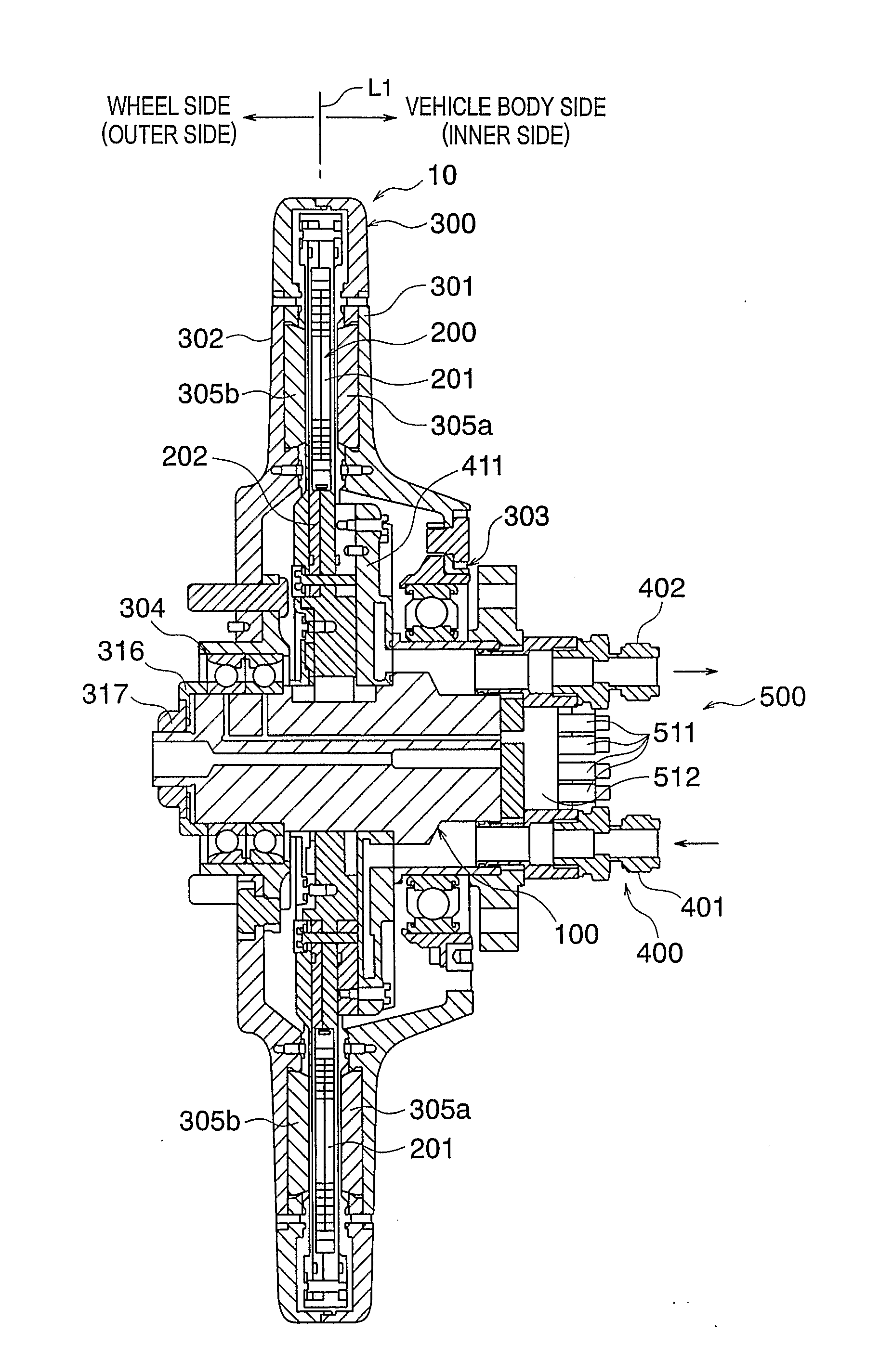
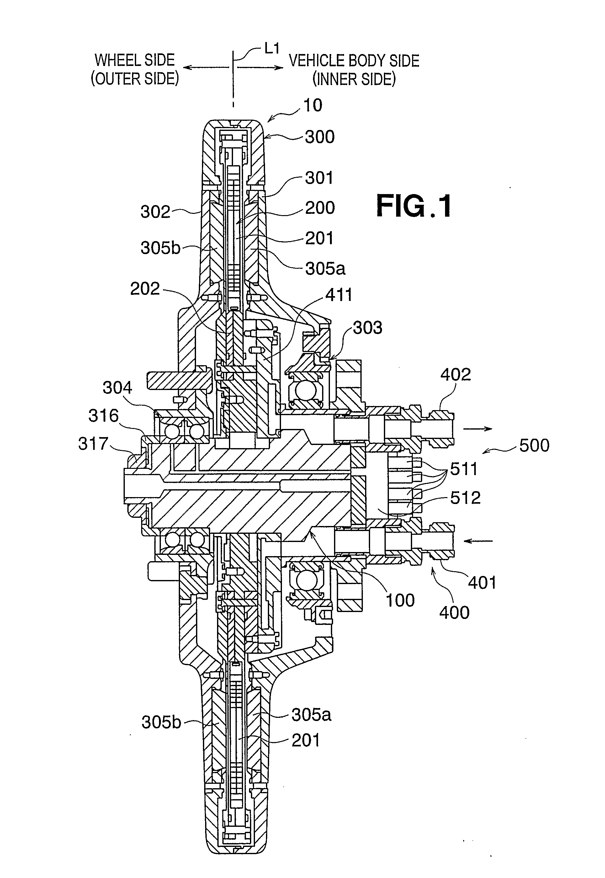
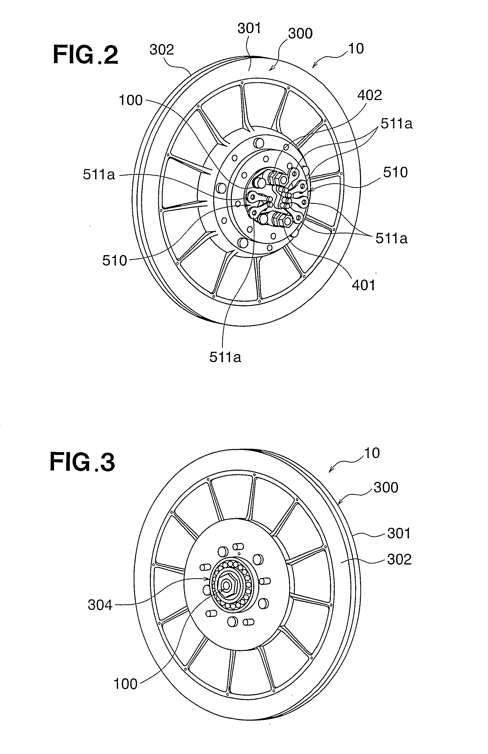
[0052]First, referring to FIGS. 1 through 5, the overall configuration of an exemplary axial type motor embodying the coil for a rotating electric machine of the present invention will be described. In this embodiment, the motor 10 will be shown by way of example as a rotating electric machine of in-wheel type used for driving a vehicle, accommodated entirely within the interior of each of a number of wheels with which the vehicle is equipped, and adapted to provide direct rotary driving of each of the wheels.

[0053]However, the coil for a r...


PUM

PropertyMeasurementUnit
depthaaaaaaaaaa
thickness D1aaaaaaaaaa

Abstract

A coil assembly for a rotating electric machine is a stator coil (201) for use in the stator of a motor (10) or the like, which comprises a coil plate (211) composed of at least two coil plate elements (211-1, 211-2) respectively provided with an internal peripheral portion and an external peripheral portion and having predetermined wiring patterns (241) formed by slits. The coil plate elements are bonded together at their internal peripheral portion and external peripheral portion while leaving the medial portion lying between the internal peripheral portion and the external peripheral portion spaced apart, so as to form the predetermined coil winding patterns (241).

Description

BACKGROUND OF THE INVENTION[0001]1. Field of the Invention[0002]The present invention relates to a coil assembly (often called simply “coil) for a rotating electric machine, to a rotating electric machine employing the same, and to a manufacturing method for these. In particular, the present invention relates to a coil assembly for an axial gap rotating electric machine, to a rotating electric machine employing the same, and to a manufacturing method for these.[0003]2. Description of the Related Art[0004]Rotating electric machines of axial type (electric motors and electric generators) equipped with a disk-shaped rotating armature coil are known in the art to date. Since rotating electric machines of axial type can be made shorter in length in the axial direction than radial gap rotating electric machines, they enjoy wide-spread use in applications in which axial length must be kept to a minimum, as, for example, in audio equipment, video recorders, computer disk drives, automotive ...

Claims


Application Information

Patent Timeline
Patent Type & Authority Applications(United States)
IPC IPC(8): H02K3/00H02K15/04H02K15/02
CPCH02K3/26H02K3/47Y10T29/4902H02K21/24Y10T29/49012H02K15/0407
Inventor IKI, TOMOTAKAOZAWA, MASARU
Owner HONDA MOTOR CO LTD
Why Eureka
Try Eureka