Motor stator structure

a technology of stator structure and motor, which is applied in the direction of engine-driven generators, transportation and packaging, electric devices, etc., can solve the problems of increasing processing cost, mechanizing completely, and difficulty in bending rectangular cross-sectioned wires in directions oblique to their surfaces, so as to prevent the leakage of synthetic resin

Inactive Publication Date: 2010-05-18
HONDA MOTOR CO LTD
View PDF7 Cites 4 Cited by
  • Summary
  • Abstract
  • Description
  • Claims
  • Application Information

AI Technical Summary

Benefits of technology

[0010]It is a second object of the present invention to ensure that when a connected portion of a wound wire of each coil in a motor stator is potted with a synthetic resin, leakage of the synthetic resin is prevented.
[0012]With the arrangement of the first feature, the neutral-point bus ring arranged along the inner peripheral portion of the stator alternately includes circumferentially-extending larger-diameter portions, radially-extending link portions, circumferentially-extending smaller-diameter portions, and the radially-extending link portions; the end of the wound wire pulled out of each coil is located between adjacent two link portions which extend radially; and the connecting terminal is connected at the first end to the end of the wound wire and at the second end to the link portion. Therefore, it is possible to form a neutral point by connecting the end of the wound wire to the neutral-point bus ring without bending the end of the wound wire into a U-shape, thereby reducing the processing cost of bending the wound wire. Further, the two link portions in the neutral-point bus ring and the end of the wound wire both extend radially, and hence it is easy to connect the link portions of the neutral-point bus ring and the ends of the wound wire to the connecting terminals.
[0016]With the arrangement of the third feature, because the wound wire is formed of a rectangular cross-sectioned wire, the lamination factor of the coil can be increased, and further it is not required to bend the rectangular cross-sectioned wire into a U-shape, thereby enhancing the effect of reducing the cost. In addition, the neutral-point bus ring is formed of the circular cross-sectioned wire, and hence it is easy to bend the neutral-point bus ring into a predetermined shape.
[0018]With the arrangement of the fourth feature, the wound-wire notch for passing the wound wire therethrough is formed in only the outer partition wall among the circumferentially extending outer and inner partition walls provided on the radially inner portion of the insulator. Therefore, when the annular space between the outer partition wall and the inner partition wall is potted with the synthetic resin after the plurality of coils whose wound wires are cut between the outer partition wall and the inner partition wall are annularly arranged to form the stator and the ends of the wound wires are connected by the connecting terminals, it is possible to prevent the synthetic resin from leaking out of the annular space. This is because the wound-wire notch of the outer partition wall is plugged by the wound wire pulled out of the coil and passes through the wound-wire notch, and the inner partition wall has no wound-wire notch.
[0022]With the arrangement of the sixth feature, when the adjacent insulators are brought into contact with each other and the ends of the inner partition walls are overlapped on each other. Therefore, it is possible to further reliably prevent the synthetic resin from leaking out of the annular space.

Problems solved by technology

On the other hand, a rectangular cross-sectioned wire can be easily bent in two directions perpendicular to each of their surfaces, but it is difficult to bend the rectangular cross-sectioned wire in directions oblique to their surfaces.
Therefore, when the rectangular cross-sectioned wire is employed as the wound wire, there is a problem: it is not possible to completely mechanize the operation of bending the end of the wound wire pulled out of the coil into a U-shape, and thus manual operation is required, greatly increasing the processing cost.
However, because the notches are plugged by the wound wire passing therethrough, unhardened synthetic resin charged into a space between the outer partition wall and the inner partition wall hardly leaks out of the notches.
When the scrap wire portion is passed through the notches in the outer partition wall and the inner partition wall, there is a disadvantage: because the scrap wire portion eventually becomes needless after completion of the wire-winding, the scrap wire portion is cut from a portion between the outer partition wall and the inner partition wall and discarded.
Thus the synthetic resin leaks out of the notch, thereby requiring an operation of wiping off the leaking synthetic resin.

Method used


Image

  • Motor stator structure
  • Motor stator structure
  • Motor stator structure

Examples


Embodiment Construction

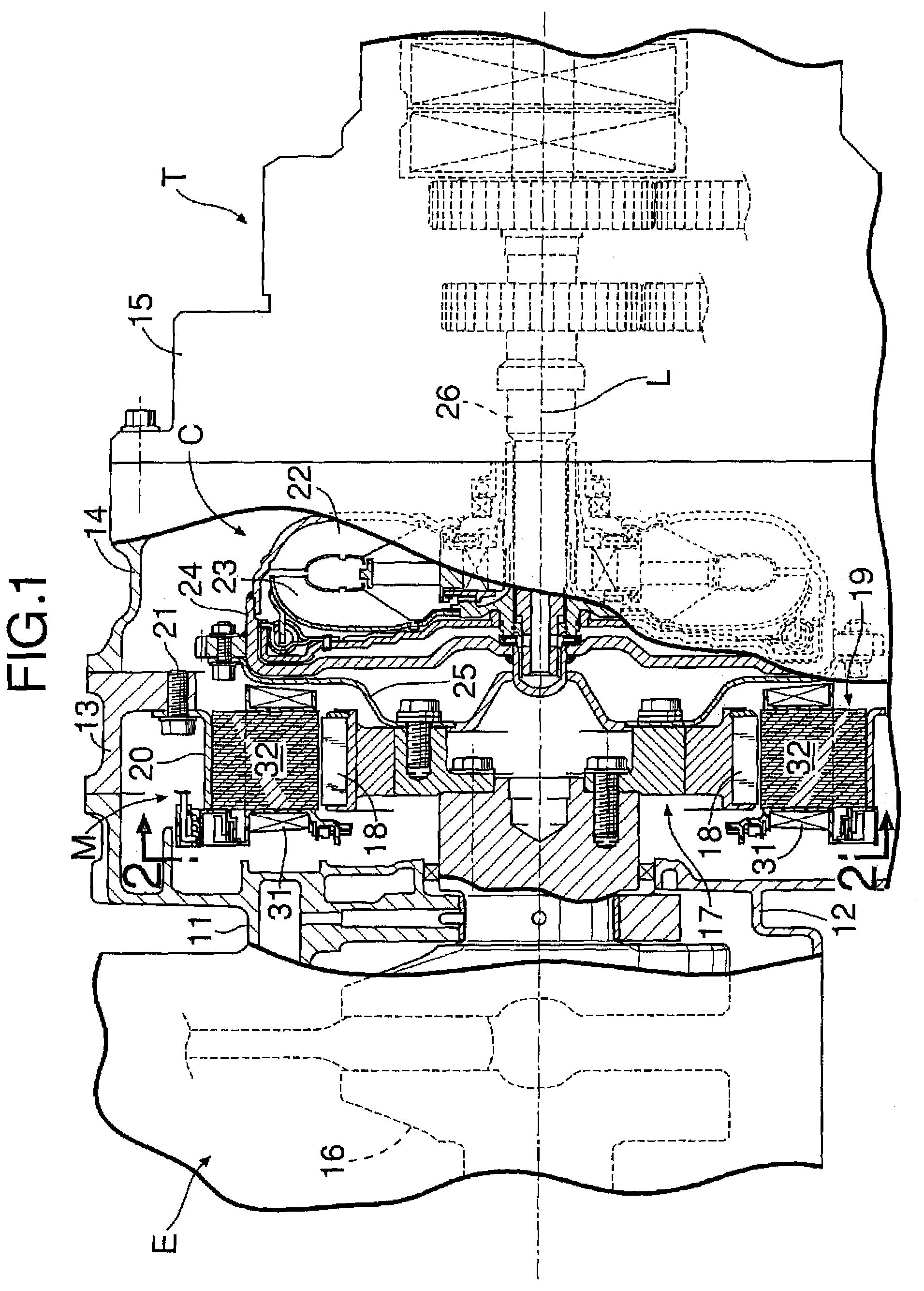
[0034]As shown in FIG. 1, a hybrid vehicle power unit includes a DC brushless motor M arranged between an engine E and a transmission T. A motor case 13, a torque converter case 14 and a transmission case 15 are coupled to right sides of a cylinder block 11 and a crankcase 12 of the engine E. A rotor 17 of the motor M is fixed to an end of a crankshaft 16 supported between the cylinder block 11 and the crankcase 12. An inner periphery of an annular stator 19 is opposed to a plurality of permanent magnets 18 fixed to an outer periphery of the rotor 17, with a predetermined air gap provided therebetween. An annular mounting bracket 20 fitted over an outer periphery of the stator 19 is fixed to the motor case 13 by a plurality of bolts 21.

[0035]A torque converter C is housed in the torque converter case 14. The torque converter C includes a turbine runner 22 and a pump impeller 23. A side cover 24 is coupled to the turbine runner 22 to cover the pump impeller 23, and connected to the r...


PUM


Abstract

In a motor stator structure, a neutral-point bus ring is arranged along an inner peripheral portion of a stator, and alternately includes a larger-diameter portion, a first link portion, a smaller-diameter portion, and a second link portion. An end of a wound wire pulled out of a coil is located between radially-extending adjacent first and second link portions. A connecting terminal is connected at one end to the end of the wound wire, and at the other end to the first and second link portions. The use of the neutral-point bus ring ensures that a neutral point can be formed without bending the end of the wound wire of the coil into a U-shape. Particularly when a rectangular cross-section wire difficult to bend is used as the wound wire, the processing cost can be reduced.

Description

RELATED APPLICATION DATA[0001]The present invention is based upon Japanese priority application Nos. 2006-184847 and 2006-184849, which are hereby incorporated in their entirety herein by reference.TECHNICAL FIELD[0002]The present invention relates to a motor stator structure comprising: a stator which includes a plurality of coils each including a wire wound around a periphery of an iron core, the coils being annularly arranged about an axis of the stator, first ends of the wires of the coils being connected to each other by connecting terminals.[0003]Also, the present invention relates to a motor stator structure comprising: a stator which includes a plurality of coils each including a wire wound around a periphery of an iron core with an insulator provided therebetween, wherein a potting with a synthetic resin is provided on portions where first ends of the wires of the coils are connected to each other by connecting terminals.BACKGROUND OF THE INVENTION[0004]A general stator of ...

Claims


Application Information

Patent Timeline
Patent Type & Authority Patents(United States)
IPC IPC(8): H02K3/52
CPCH02K3/522H02K2203/09H02K5/225B60L2220/50B60L50/15Y02T10/64Y02T10/7072
Inventor OKADA, TOMOYUKIKONO, MICHIHISASATO, HIROYUKINAKAJIMA, MINORU
Owner HONDA MOTOR CO LTD
Why Eureka
Try Eureka