Eureka AIR delivers breakthrough ideas for toughest innovation challenges, trusted by R&D personnel around the world.

Electromagnetic wave transmission medium

a transmission medium and electromagnetic wave technology, applied in the direction of waveguides, electrical devices, coupling devices, etc., can solve the problems of increasing the machining accuracy of maintaining a transmission characteristic, increasing the transmission loss, and deteriorating durability, so as to achieve easy machining, high mass productivity, and widen the impedance range matched by the ridge

Active Publication Date: 2010-01-07
YOKOWO CO LTD
View PDF6 Cites 9 Cited by
  • Summary
  • Abstract
  • Description
  • Claims
  • Application Information

AI Technical Summary

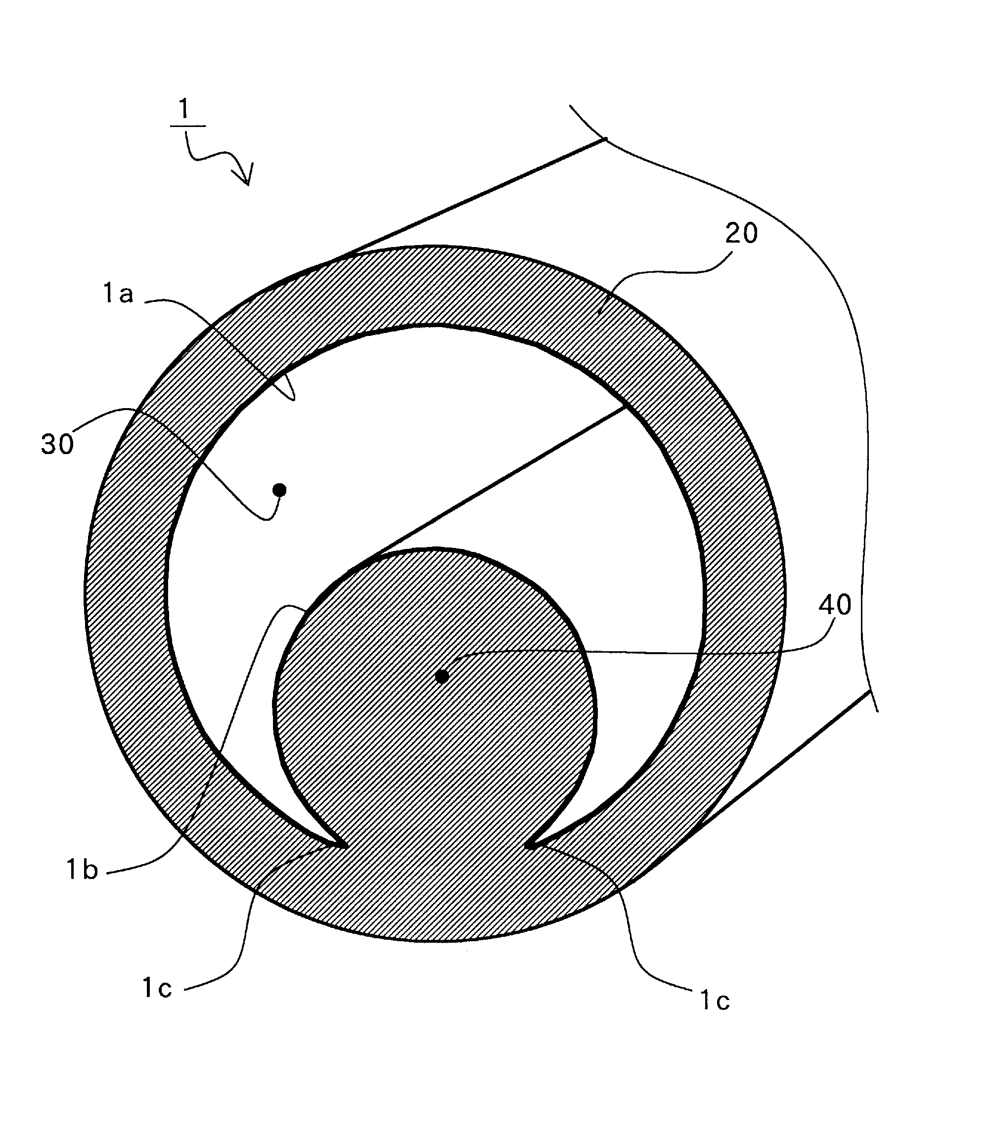
Benefits of technology

[0006]It is an object of the present invention to provide an electromagnetic wave transmission medium with a novel structure which does not increase the manufacturing costs even if a frequency band of an electromagnetic wave to be used is high, and does not adversely affect the transmission mode even if the transmission medium is bent.
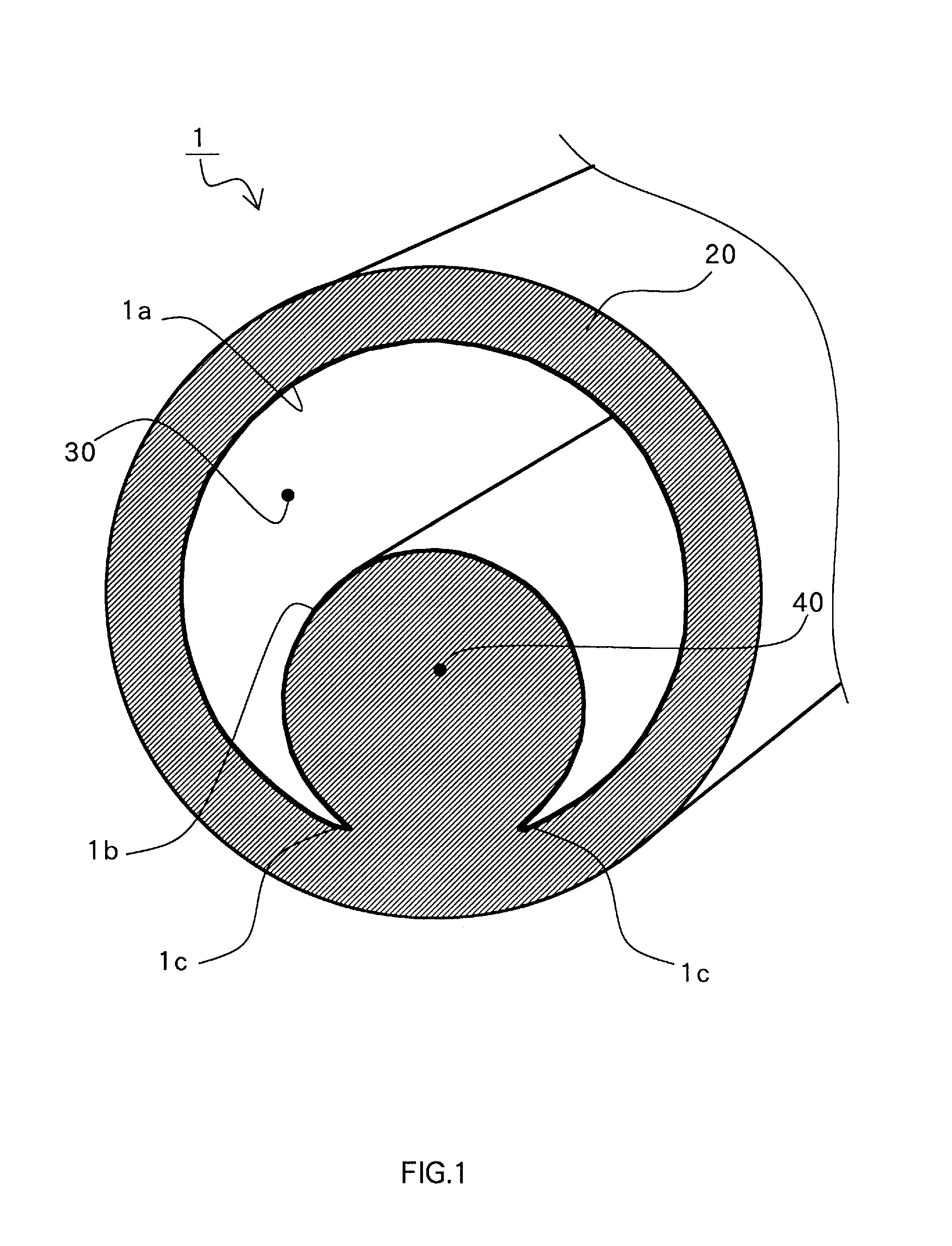
[0011]The internal space may be a free space, and the internal space may be filled with a dielectric material. From the viewpoint of enhancing an added value, another transmission medium is arranged in an area surrounded by the arc of the second circle. As a result, two transmission lines can be formed by one transmission line.
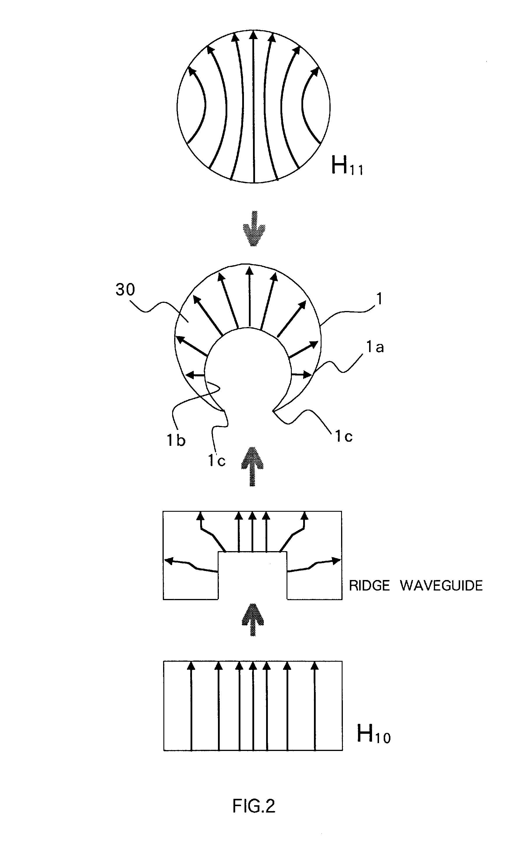
[0012]In the electromagnetic wave transmission medium according to the present invention, the cylindrical tube is molded so that the cross-sectional shape of the cylindrical tube in a direction orthogonal to the tube axis is uniform in the tube axis, and an impedance range matched by the ridge can be widened. Therefore, even if the frequency is high (for example, even at the millimeter waveband), there are advantages in that machining is easy, and the mass productivity is high. The cross-sectional shape is circular in surface, and therefore, the transmission medium is resistant to bending in all directions. Particularly, the ridge acts as a reinforcement member when the tube is bent, and the transmission mode can be stabilized. As a result, it is possible to suppress the deterioration of the characteristic.

Problems solved by technology

However, the diameter of the coaxial line needs to be thinner as the frequency increases, and therefore, problems arise such as an increase in transmission loss, an increase in machining accuracy for maintaining a transmission characteristic, deterioration in durability, and so on.
In such a thin coaxial line, not only the loss is increased but also a slight mechanical error greatly affects the transmission characteristic.
In addition, for the flexible waveguide to realize a structure in which millimeter waveband exceeding, for example, 30 [GHz] can be used, a complicated and high-level processing technique is required.
Also, such a thin flexible waveguide lacks in durability.
However, such a waveguide has a large transmission loss and insufficient flexibility.
Further, the transmission mode becomes unstable when the waveguide is bent because the cross section is ellipsoidal, resulting in such a problem that the characteristic changes.

Method used


Image

  • Electromagnetic wave transmission medium
  • Electromagnetic wave transmission medium
  • Electromagnetic wave transmission medium

Examples


modified example

[0045]The electromagnetic wave transmission medium according to this embodiment can be configured with any structure other than the structure described above. FIGS. 8A to 8E are cross-sectional views showing modified examples thereof, and the outer sheath 20 is omitted for convenience.

[0046]FIG. 8A shows a structure in which a dielectric material is installed in the transmission space 30, and the depression space 40 is a free space. FIG. 8B shows a structure in which the arc angles of the second circle 1b are 90 degrees (180 degrees in total) to the right and left from the symmetric axis, respectively. FIG. 8C shows a structure in which the transmission space 30 is a free space, and the ridge formed by the second circle is hollow, and the arc angle of the second circle 1b is 360 degrees in total. FIG. 8D shows a structure in which a dielectric material is installed in the depression space 40 in the structure of FIG. 8C. FIG. 8E shows a structure in which a conductor line 5 coated wi...


PUM


Abstract

Provided is an electromagnetic wave transmission medium which is suited for mass production and does not affect a transmission mode. The electromagnetic wave transmission medium includes, as a main element, a flexible cylindrical tube (1) molded so that a cross-sectional shape of the cylindrical tube in a direction orthogonal to a tube axis is uniform in a direction of the tube axis. The cylindrical tube (1) includes an inner wall formed of a conductive layer having a thickness equal to or more than a skin depth. The cross-sectional shape is a circular ridge waveguide shape having a ridge (1b) which is oriented to a cylindrical axis and is symmetric with respect to a center, and the ridge (1b) has a structure to be fed with electricity.

Description

CROSS REFERENCE TO RELATED APPLICATION[0001]This application claims priority to Japanese Patent Application No. 2008-176173, filed Jul. 4, 2008, which is incorporated herein by reference in its entirety.FIELD OF THE INVENTION[0002]The present invention relates to an electromagnetic wave transmission medium with a novel structure for transmitting frequencies of a microwave band or higher.BACKGROUND[0003]Examples of the electromagnetic wave transmission medium for connecting high frequency devices to each other whose relative position cannot be determined with precision or one or both of which are changed in position include a coaxial line and a flexible waveguide. The coaxial line is frequently used for its excellent flexibility and relatively inexpensive price. However, the diameter of the coaxial line needs to be thinner as the frequency increases, and therefore, problems arise such as an increase in transmission loss, an increase in machining accuracy for maintaining a transmissio...

Claims


Application Information

Patent Timeline
Patent Type & Authority Applications(United States)
IPC IPC(8): H01P5/103H01P3/127
CPCH01P3/123H01P5/103H01P3/14H01P3/127
Inventor YANAGISAWA, WASUKEMIZUTANI, HIROSHIISHII, YASUNOBUSUZUKI, MITSUHIROHORIE, RYO
Owner YOKOWO CO LTD
Why Eureka
Eureka Blog
Learn More